1. Overview
FM (Frequency Modulation) and AM (Amplitude Modulation) broadcasting, as two common analog broadcast modulation technologies, may seem somewhat primitive today as communication technology increasingly trends towards digitalization, networking, and intelligence. However, FM and AM broadcasting still hold significant positions in certain specific domains. For example, in urban areas, car radios have a vast listener base. During natural disasters or emergencies, analog broadcasting can also provide more stable and reliable communication assurance. Therefore, testing FM/AM broadcasting is necessary. FM and AM transmitters, as crucial equipment in radio communication, have performance that directly impacts communication quality and the effectiveness of receiver signal demodulation. Hence, testing FM and AM transmitters is a vital step in ensuring they can stably provide broadcast services to users.
2. Background
Analog broadcast technology has developed many mature test methods and standards to date. Standards such as *GY/T169-2001 Technical Requirements and Measurement Methods for VHF FM Broadcast Transmitters* and *GY/T225-2007 Technical Requirements and Measurement Methods for Medium and Short Wave AM Broadcast Transmitters* provide relatively detailed descriptions of relevant test metrics and methods for FM/AM broadcast transmitters. However, how to complete the tests more comprehensively and efficiently has become the primary concern for testers. The traditional test method familiar to engineers involves using the once industry-benchmark product, the FMAB. However, its large size added considerable burden to testing, and it is now long discontinued. Due to the lack of a comprehensive system test solution, many may opt to test only FM broadcasting, which sees more application, and might simply use a radio receiver to test the reception effect for demodulated audio.
Based on the above, this article introduces a new automated test system for FM/AM transmitter testing: iBroadcast. Different from traditional methods, this system can perform various metric tests from both the RF (Radio Frequency) and audio levels. This system consists of automation control and information management software, the Broadcast Modulation Analyzer RWC2500A Plus, and the Audio Analyzer A5. The Broadcast Modulation Analyzer RWC2500A Plus offers testing capabilities and performance comparable to the FMAB while maintaining a compact form factor. The following sections provide a more detailed introduction to this system.
3. System Introduction
The iBroadcast automated test system is suitable for testing against various relevant standards and can automatically configure parameters based on the standard selected by the user. It supports RF-level metric testing, such as: Carrier Power, Frequency Deviation, Modulation Depth, etc. It also supports testing demodulated audio metrics, such as: Harmonic Distortion (THD), Signal-to-Noise Ratio (SNR), Crosstalk, etc. The overall system block diagram is shown in Figure 1.
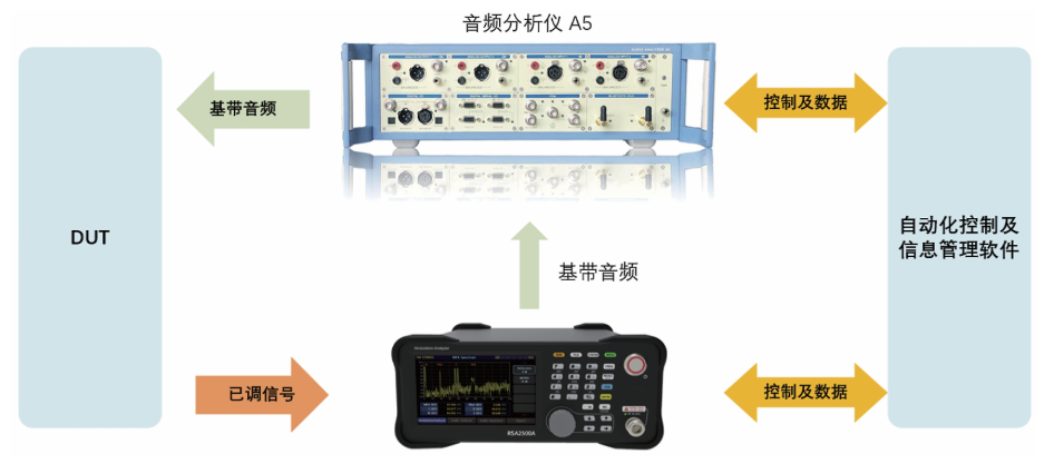
Figure 1
First, the Audio Analyzer A5 provides the baseband audio signal and outputs it to the Device Under Test (DUT) transmitter for modulation. The DUT transmitter then inputs the modulated signal into the Broadcast Modulation Analyzer RWC2500A Plus for RF-level metric analysis. The RWC2500A Plus demodulates the modulated signal and outputs the demodulated audio to the A5 for audio-level metric analysis. Throughout the testing process, the equipment can be controlled in real-time, and information managed, via the automation control and information management software.
4. Introduction to Core Function Software
The automation control and information management software enables the control and management of the Broadcast Modulation Analyzer RWC2500A Plus and the Audio Analyzer A5 during testing. As shown in Figure 2, testers log into the software using an account to perform tests. Different testers can use different account credentials, helping to protect critical test information and prevent accidental changes to key settings.
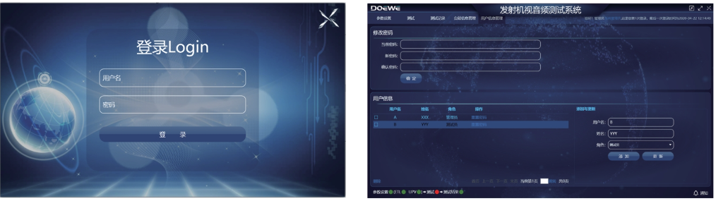
Figure 2
The software provides multiple functional interfaces, including: Parameter Setting Interface, Station Information Management Interface, Test Interface, and Test Record Interface.
The Parameter Setting Interface (Figure 3, left) is mainly divided into Instrument Settings and Test Settings. The Instrument Settings section allows configuration of Carrier Frequency, Instrument Connection, Broadcast Standard (Stereo/MONO), Baseband Audio Output Type (Analog/Digital), Baseband Audio Output Interface (Unbalanced/Balanced), and Mono Baseband Audio Output Interface. The Test Settings section allows selection of test items, test methods, measurement interval time, configuration of level units, and setting upper/lower limits for metrics based on the selected test items and hardware configuration/test requirements.
The Station Information Management Interface (Figure 3, right) allows adding stations and transmitters within stations. On the right side of the station information section, station name and location can be entered. For added stations, corresponding transmitter information can be set: Test Mode, Frequency, Channel, Broadcast Content, Device Type (Main/Backup), Manufacturer, Model, and Commissioning Date.
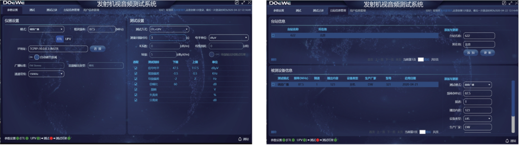
Figure 3
The Test Interface (Figure 4) allows automated testing by selecting the station under test and a specific transmitter within that station. It supports real-time viewing of the "Status" column to observe the current state of the test item. If a result exceeds the limit after testing is complete, it will be highlighted in red. Sub-menus allow viewing test data for Frequency Response, Distortion, and Separation.
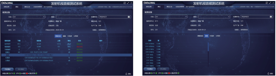
Figure 4
The Test Record Interface (Figure 5, left) allows searching completed test records and supports generating test reports. Fuzzy queries can be performed based on Detection Mode, Station Name, Equipment, Detection Date, and Keywords. Entering an indicator name in the "Fuzzy Query" box will search for test records containing that metric test. Entered search information can also be cleared via Reset. As shown in Figure 5 (right), test reports support export in PDF format.
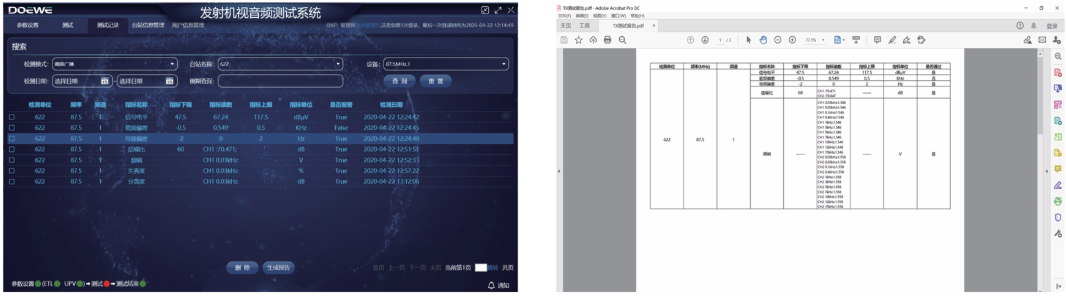
Figure 5
5. Hardware Introduction
This test system employs high-performance hardware devices. Besides working with the software for automated testing, they can also be used individually for more tests. The core functions of the devices are as follows.
Broadcast Modulation Analyzer RWC2500A Plus:
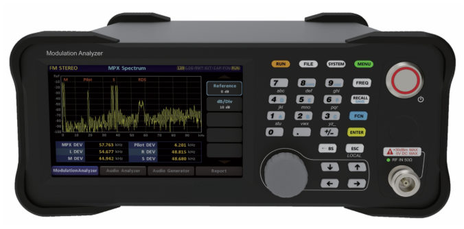
1)Supports high-precision AM/FM demodulation and parameter analysis, including Stereo FM.
2)Local Oscillator frequency accuracy up to 1ppb, SNR > 80dB.
3)Can output demodulated baseband audio, supports Balanced/Unbalanced/Digital interfaces.
4)Can display RF spectrum, and spectrum/waveform of demodulated audio in real-time.
5)Supports audio analysis, measuring Distortion (THD), Signal-to-Noise Ratio (SNR), Frequency Response, Separation, etc.
6)Supports audio generation, outputting Tone or Sweep signals, supports multiple interfaces.
7)Supports custom upper/lower limits for test items; indicators exceeding limits are prompted in real-time.
8)Supports test result overview and data export; generates reports with one click.
9)Equipped with a color touch screen and buttons for cooperative operation.
Audio Analyzer A5:
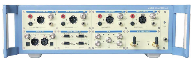
1)Standard support for SPDIF/TOSLINK/AES/EBU digital interfaces.
2)Supports digital interface expansion for BT/HDMI/I2S/PDM, etc.
3)Comprehensive and powerful electroacoustic analyzer functions.
4)Codeless automation and comprehensive API interface.
5)Supports LabVIEW, VB.NET, C#.NET.
6)Automatically generates test reports in various formats.
7)Up to 60 test functions, including Oscilloscope, Spectrum Analyzer, Continuous Fast Sweep, etc.
For more detailed information about this test solution and usage methods, please consult Beijing Doewe Technologies Co., Ltd.