1. Overview
1.1 Test Purpose
This solution provides a reference audio test methodology for R&D and production of smart video doorbell products. It employs scientific measurement techniques to evaluate audio performance metrics (e.g., frequency response, THD+N, noise, SNR, audio spectrum), delivering visualized data guidance to enhance product quality control.
1.2 Test Indicators
1.2.1 Frequency Response
Frequency response refers to the output signal level of the DUT when it is excited by excitation signals of different frequencies at a known level. The most commonly used method is to scan sine wave signals from the lowest frequency to the highest frequency within the frequency range of the DUT and plot the results.
In the sweep test, the sweep level should be determined first. Sweep can be carried out at low level, but noise or other stray signals may appear in the response; sweep can also be carried out at high level, but high distortion may occur.
1.2.2 THD+N
THD+N is the abbreviation of total harmonic distortion plus noise. Harmonic distortion refers to the unnecessary tones added to the original audio signal, which are the tones related to the harmonics of the original signal. When the signal is a sine wave with frequency f1, the harmonics are f2, f3, etc., which are integer multiples of the original tone. Total harmonic distortion is the sum of all harmonics in the bandwidth of the DUT.
It has always been the case that total harmonic distortion and noise are tested together. Some people may ask why harmonics and noise are not tested separately. This is because when testing total harmonic plus noise, fast Fourier transform (FFT) testing is used, and it is difficult to separate harmonics and noise, but testing them together is relatively simple. Of course, ABTEC audio analyzer can view the total harmonics, noise and the distribution of harmonic signals from f2 to f10 in real time as needed.
1.2.3 Noise and Signal-to-Noise Ratio
Definition: The term "noise" refers to any unwanted signal, including AC power hum, stray magnetic field interference from circuit devices, etc. A filter must be selected for noise measurement. Generally, noise measurement only refers to the random noise with energy distributed in the broadband, as well as the unwanted coherent signals such as hum and interference.
Unit: Generally, decibel (dB) is used to measure the intensity of noise, and signal-to-noise ratio (S/N) is used to measure the degree of influence of noise on the useful signal.
How much noise is too much?
It depends on the loudness of the signal.
Signal-to-noise ratio SNR is a measure of this difference. The signal-to-noise ratio refers to the ratio of the signal to the noise in an electronic device or electronic system. In the process of testing the signal-to-noise ratio, in the past, two steps were required: first, input an excitation level to the DUT, the instrument obtained the size of the signal, then turned off the signal, obtained the noise signal, and then compared and calculated the value of the signal-to-noise ratio. Now the instrument can automatically control the signal and calculate the data.
1.3 Test System Principle
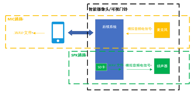
The audio system of general intelligent video doorbell products can be divided into microphone audio path and speaker audio path. The microphone audio path is that the microphone collects the sound signal and converts it into an analog audio electrical signal. The subsequent system receives the analog audio electrical signal from the microphone and converts it into a digital audio signal, which is transmitted to the mobile terminal through the wireless network. The mobile terminal converts it into a .wav format audio file through the corresponding APP application program. The speaker audio path is that the .wav file stored in the SD card or the local memory of the intelligent video doorbell product is converted into an analog audio electrical signal and transmitted to the speaker, and the speaker receives the analog audio electrical signal and converts it into a sound signal to send out.
2. Microphone Path Test
2.1 Whole Machine Test
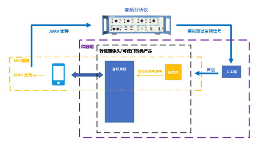
For the whole machine test, professional audio analyzer and artificial mouth are selected as the test instruments, which can provide analog and digital audio test signals and sound wave signals. During the test, the artificial mouth and the DUT (product) should be installed in the professional soundproof box to avoid the influence of environmental sound on the test system. The professional audio analyzer sends the test sound wave signal to the DUT (product), and the DUT outputs the .wav format audio file to the professional audio analyzer to form a closed-loop test system.
2.1.1 THD+N Test
Test steps:
1)Calibrate the artificial mouth with a standard microphone;
2)Use the audio analyzer to generate an analog test audio signal with a frequency of 1KHz and an amplitude of 1V;(Note: The amplitude is tentatively set to 1V, and the actual test is adjusted according to the human voice size in the application environment.)
3)Use the corresponding APP application program to record the test audio signal as a .wav format audio file;
4)Use the audio analyzer to analyze the .wav format audio file, observe and record the THD+N index of the product (which can be analyzed in combination with the audio spectrum);
5) Repeat the above steps for many times to avoid test contingency.
2.1.2 Spectrum Analysis
Test steps:
1)Calibrate the artificial mouth with a standard microphone (if it has been calibrated in the previous test, it does not need to be calibrated again in this test);
2)Use the audio analyzer to generate an analog test audio signal with a frequency of 1KHz and an amplitude of 1V;(Note: The amplitude is tentatively set to 1V, and the actual test is adjusted according to the human voice size in the application environment.)
3)Use the corresponding APP application program to record the test audio signal as a .wav format audio file;
4)Use the audio analyzer to analyze the .wav format audio file, save and observe the audio spectrum analysis;
5)Repeat the above steps for many times to avoid test contingency.
2.1.3 Signal-to-Noise Ratio Test
Test steps:
1)Calibrate the artificial mouth with a standard microphone (if it has been calibrated in the previous test, it does not need to be calibrated again in this test);
2)Use the audio analyzer to generate a signal-to-noise ratio test audio (the first half has a frequency of 1KHz and an amplitude of 1V, and the second half does not generate an audio signal);(Note: The amplitude is tentatively set to 1V, and the actual test is adjusted according to the human voice size in the application environment.)
3)Use the corresponding APP application program to record the test audio signal as a .wav format audio file;
4)Use the audio analyzer to analyze the .wav format audio file, observe and record the signal-to-noise ratio index of the product;
5)Repeat the above steps for many times to avoid test contingency.
2.1.4 Frequency Response Test
Test steps:
1)Calibrate the artificial mouth with a standard microphone (if it has been calibrated in the previous test, it does not need to be calibrated again in this test);
2)Use the audio analyzer to generate a step sweep test audio (frequency range 20Hz-20kHz, linear sweep, sweep points 30, amplitude 1V);(Note: The frequency range and the number of sweep points are determined according to the audio processing range of the actual DUT, the amplitude is tentatively set to 1V, and the actual test is adjusted according to the human voice size in the application environment.)
3)Use the corresponding APP application program to record the test audio signal as a .wav format audio file;
4)Use the audio analyzer to analyze the .wav format audio file, observe and record the frequency response index of the product;
5)Repeat the above steps for many times to avoid test contingency.
2.2 Audio Acquisition and Coding System Test
The door load part of the intelligent video doorbell will collect and encode the signal input by the microphone, and this part also needs to be tested. The test instrument selects a professional audio analyzer, which can provide analog and digital audio test signals. The professional audio analyzer sends the analog test audio electrical signal to the subsequent system (skipping the microphone), and the subsequent system outputs the .wav format audio file to the professional audio analyzer to form a closed-loop test system.
2.2.1 THD+N Test
Test steps:
1)Use the audio analyzer to generate an analog test audio signal with a frequency of 1KHz and an amplitude of 1V;
2)Use the corresponding APP application program to record the test audio signal as a .wav format audio file;
3)Use the audio analyzer to analyze the .wav format audio file, observe and record the THD+N index of the product (which can be analyzed in combination with the audio spectrum);
4)Repeat the above steps for many times to avoid test contingency.
2.2.2 Spectrum Analysis
Test steps:
1)Use the audio analyzer to generate an analog test audio signal with a frequency of 1KHz and an amplitude of 1V;(Note: The amplitude is tentatively set to 1V, and the actual test is adjusted according to the human voice size in the application environment.)
2)Use the corresponding APP application program to record the test audio signal as a .wav format audio file;
3)Use the audio analyzer to analyze the .wav format audio file, save and observe the audio spectrum analysis;
4)Repeat the above steps for many times to avoid test contingency.
2.2.3 Signal-to-Noise Ratio Test
Test steps:
1)Use the audio analyzer to generate a signal-to-noise ratio test audio (the first half has a frequency of 1KHz and an amplitude of 1V, and the second half does not generate an audio signal);
2)Use the corresponding APP application program to record the test audio signal as a .wav format audio file;
3)Use the audio analyzer to analyze the .wav format audio file, observe and record the signal-to-noise ratio index of the product;
4)Repeat the above steps for many times to avoid test contingency.
2.2.4 Frequency Response Test
Test steps:
1)Use the audio analyzer to generate a step sweep test audio (frequency range 20Hz-20kHz, linear sweep, sweep points 30, amplitude 1V);
2)Use the corresponding APP application program to record the test audio signal as a .wav format audio file;
3)Use the audio analyzer to analyze the .wav format audio file, observe and record the frequency response index of the product;
4)Repeat the above steps for many times to avoid test contingency.
2.3 Microphone Component Test
For the microphone component test, the test instruments are professional audio analyzer and artificial mouth, which can provide analog and digital audio test signals and sound wave signals. During the test, the artificial mouth and the microphone should be installed in the professional soundproof box to avoid the influence of environmental sound on the test system. The professional audio analyzer sends the test sound wave signal to the microphone, and the microphone converts the sound wave signal into an analog audio signal to the professional audio analyzer to form a closed-loop test system.
2.3.1 THD+N Test
Test steps:
1)Calibrate the artificial mouth with a standard microphone;
2)Use the audio analyzer to generate an analog test audio signal with a frequency of 1KHz and an amplitude of 1V;
3)Use the audio analyzer to analyze the analog audio signal output by the microphone, observe and record the THD+N index of the product (which can be analyzed in combination with the audio spectrum);
4)Repeat the above steps for many times to avoid test contingency.
2.3.2 Spectrum Analysis
Test steps:
1)Calibrate the artificial mouth with a standard microphone (if it has been calibrated in the previous test, it does not need to be calibrated again in this test);
2)Use the audio analyzer to generate an analog test audio signal with a frequency of 1KHz and an amplitude of 1V; (Note: The amplitude is tentatively set to 1V, and the actual test is adjusted according to the human voice size in the application environment.)
3)Use the audio analyzer to analyze the analog audio signal output by the microphone, save and observe the audio spectrum analysis;
4)Repeat the above steps for many times to avoid test contingency.
2.3.3 Signal-to-Noise Ratio Test
Test steps:
1)Calibrate the artificial mouth with a standard microphone (if it has been calibrated in the previous test, it does not need to be calibrated again in this test);
2)Use the audio analyzer to generate a signal-to-noise ratio test audio (the first half has a frequency of 1KHz and an amplitude of 1V, and the second half does not generate an audio signal);
3)Use the audio analyzer to analyze the analog audio signal output by the microphone, observe and record the signal-to-noise ratio index of the product;
4)Repeat the above steps for many times to avoid test contingency.
2.3.4 Frequency Response Test
Test steps:
1)Calibrate the artificial mouth with a standard microphone (if it has been calibrated in the previous test, it does not need to be calibrated again in this test);
2)Use the audio analyzer to generate a step sweep test audio (frequency range 20Hz-20kHz, linear sweep, sweep points 30, amplitude 1V);
3)Use the audio analyzer to analyze the analog audio signal output by the microphone, observe and record the frequency response index of the product;
4)Repeat the above steps for many times to avoid test contingency.
3. Speaker Path Test
3.1 Whole Machine Test
For the whole machine test, the test instruments are professional audio analyzer and artificial ear, which can receive analog and digital audio test signals and sound wave signals. During the test, the artificial ear and the DUT (product) should be installed in the professional soundproof box to avoid the influence of environmental sound on the test system. The pre-made .wav format standard audio test file is stored in the SD card in advance, and the SD card is inserted into the DUT (product). The artificial ear receives the sound wave signal from the speaker of the DUT (product) and converts it into an analog audio electrical signal to output to the professional audio analyzer for the whole machine test.
3.1.1 THD Test
Test steps:
1)Calibrate the artificial ear with a standard artificial mouth;
2)Control the DUT (product) to send the pre-made THD test audio file (1KHz single tone);
3)Use the audio analyzer to analyze the audio signal collected by the artificial ear, observe and record the THD index of the product (which can be analyzed in combination with the audio spectrum and time-domain waveform);
4)Repeat the above steps for many times to avoid test contingency.
3.1.2 Abnormal Sound (Rub & Buzz) Test
Test steps:
1)Calibrate the artificial ear with a standard artificial mouth (if it has been calibrated in the previous test, it does not need to be calibrated again in this test);
2)Control the DUT (product) to send the pre-made abnormal sound (Rub & Buzz) test audio file (1KHz single tone);
3)Use the audio analyzer to analyze the audio signal collected by the artificial ear, observe and record the abnormal sound (Rub & Buzz) index of the product;
4)Repeat the above steps for many times to avoid test contingency.
3.1.3 Spectrum Analysis
Test steps:
1)Calibrate the artificial ear with a standard artificial mouth (if it has been calibrated in the previous test, it does not need to be calibrated again in this test);
2)Control the DUT (product) to send the pre-made test audio file (1KHz single tone);
3)Use the audio analyzer to analyze the audio signal collected by the artificial ear, save and observe the audio spectrum analysis;
4)Repeat the above steps for many times to avoid test contingency.
3.1.4 Frequency Response Test
Test steps:
1)Calibrate the artificial ear with a standard artificial mouth (if it has been calibrated in the previous test, it does not need to be calibrated again in this test);
2)Control the DUT (product) to send the pre-made sweep test audio file (frequency range 20Hz-20kHz, linear sweep, sweep points 30);
3)Use the audio analyzer to analyze the audio signal collected by the artificial ear, observe and record the frequency response index of the product;
4)Repeat the above steps for many times to avoid test contingency.
3.2 Audio Decoding System Test
The audio decoding system following the speaker also needs to be tested. The test instrument selects a professional audio analyzer, which can receive analog/digital audio test signals. The pre-made .wav format standard audio test file is stored in the SD card in advance, and the SD card is inserted into the DUT (product). The subsequent system converts the .wav format standard audio test file into an analog audio electrical signal and outputs it to the professional audio analyzer for the subsequent system test.
3.2.1 THD Test
Test steps:
1)Control the DUT (product) to send the pre-made THD test audio file (1KHz single tone);
2)Use the audio analyzer to analyze the analog audio signal output by the subsequent system, observe and record the THD index of the product (which can be analyzed in combination with the audio spectrum and time-domain waveform);
3)Repeat the above steps for many times to avoid test contingency.
3.2.2 Abnormal Sound (Rub & Buzz) Test
Test steps:
1)Control the DUT (product) to send the pre-made abnormal sound (Rub & Buzz) test audio file (1KHz single tone);
2)Use the audio analyzer to analyze the analog audio signal output by the subsequent system, observe and record the abnormal sound (Rub & Buzz) index of the product;
3)Repeat the above steps for many times to avoid test contingency.
3.2.3 Spectrum Analysis
Test steps:
1)Control the DUT (product) to send the pre-made test audio file (1kHz single tone);
2)Use the audio analyzer to analyze the analog audio signal output by the subsequent system, save and observe the audio spectrum analysis;
3)Repeat the above steps multiple times to avoid test contingency.
3.2.4 Frequency Response Test
Test steps:
1)Control the DUT (product) to send the pre-made sweep test audio file (frequency range 20Hz–20kHz, linear sweep, 30 sweep points);
2)Use the audio analyzer to analyze the analog audio signal output by the subsequent system, observe and record the product's frequency response index;
3)Repeat the above steps multiple times to avoid test contingency.
3.3 Speaker Component Test
For speaker component testing, professional audio analyzers and artificial ears are selected as testing instruments, which can receive analog and digital audio test signals and sound wave signals. During the test, the artificial ear and the DUT speaker should be placed in a professional soundproof box to avoid environmental sound interference with the test system. The professional audio analyzer sends analog test audio electrical signals to the DUT speaker, and the artificial ear receives the sound wave signals from the DUT speaker, converts them into analog audio electrical signals, and outputs them to the professional audio analyzer for closed-loop testing.
3.3.1 THD Test
Test steps:
1)Calibrate the artificial ear with a standard artificial mouth;
2)Use the audio analyzer to generate an analog test audio signal with a frequency of 1kHz and an amplitude of 200mV;
3)Use the audio analyzer to analyze the audio signal collected by the artificial ear, observe and record the product's THD index (analysis can be combined with audio spectrum and time-domain waveform);
4)Repeat the above steps multiple times to avoid test contingency.
3.3.2 Spectrum Analysis
Test steps:
1)Calibrate the artificial ear with a standard artificial mouth (if calibrated in the previous test, no need to calibrate again for this test);
2)Use the audio analyzer to generate an analog test audio signal with a frequency of 1kHz and an amplitude of 200mV;
3)Use the audio analyzer to analyze the audio signal collected by the artificial ear, save and observe the audio spectrum analysis;
4)Repeat the above steps multiple times to avoid test contingency.
3.3.3 Abnormal Sound (Rub & Buzz) Test
Test steps:
1)Calibrate the artificial ear with a standard artificial mouth (if calibrated in the previous test, no need to calibrate again for this test);
2)Use the audio analyzer to generate an analog test audio signal with a frequency of 1kHz and an amplitude of 200mV;
3)Use the audio analyzer to analyze the audio signal collected by the artificial ear, observe and record the product's abnormal sound (Rub & Buzz) index;
4)Repeat the above steps multiple times to avoid test contingency.
3.3.4 Frequency Response Test
Test steps:
1)Calibrate the artificial ear with a standard artificial mouth (if calibrated in the previous test, no need to calibrate again for this test);
2)Use the audio analyzer to generate a sweep test audio (frequency range 20Hz–20kHz, linear sweep, 30 sweep points, amplitude 200mV);
3)Use the audio analyzer to analyze the audio signal collected by the artificial ear, observe and record the product's frequency response index;
4)Repeat the above steps multiple times to avoid test contingency.
4. Summary
Based on this test scheme, objective and repeatable quality evaluation can be conducted for the audio transmission and processing chain of intelligent video doorbell products. For both R&D and production, it can provide quantitative and visual parameter comparisons. In case of product quality issues, it can effectively locate faults and quickly feedback to the R&D department for optimizing the corresponding product modules.
The core testing equipment for the entire test is the A5 audio analyzer, which features a highly user-friendly operation interface and provides reliable testing accuracy, currently recognized by the industry.
Considering different requirements for test parameters, number of channels, and accuracy, our company can also recommend other audio analyzers in the same series, such as A2/A4/A7/A8/A9, etc. Welcome to inquire.