1. Overview
This article, based on the testing procedures outlined in "GYT 274-2013 Technical Specifications and Measurement Methods for Digital Mixers," will introduce how to use an audio analyzer to test the analog input to analog output interface specifications of a digital mixer.
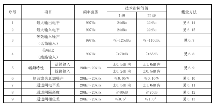
Figure 1
Figure 1 shows all the test specifications and their requirements for the analog input to analog output interface as stipulated by the standard, including: Maximum Output Level, Maximum Input Level, Equivalent Input Noise (Mic Input), Signal-to-Noise Ratio (Line Input), Amplitude-Frequency Response, Total Harmonic Distortion plus Noise (THD+N), Level Difference Between Channels, Crosstalk (Isolation) Between Channels, and Phase Difference Between Channels. The following sections will primarily focus on how to use an audio analyzer to test Signal-to-Noise Ratio (S/N), Amplitude-Frequency Response, and Total Harmonic Distortion plus Noise (THD+N).
2. Test Preparation
2.1 Connection Setup
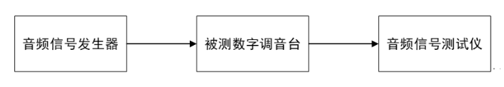
Figure 2
The audio analyzer outputs the test audio signal to the Device Under Test (DUT) mixer. The audio signal passes through the mixer and is then looped back to the audio analyzer for analysis. All subsequent tests follow this method of connecting the audio analyzer to the DUT.
2.2 Mixer Test State Configuration
According to the standard method description: "Except for the microphone input channel preamplifier gain of the digital mixer being set to ON (set according to the device's nominal value, suggested value 54 dB), the preamplifier gain for other input channels is set to 0 dB. Functions such as pan adjustment, equalization control, and compression/limiting processing on all channels should be turned off or bypassed. During measurement, only the fader of the channel under test is set to the 0 position; faders of all other input channels are set to the -∞ position. If the digital mixer has a master output control fader, it should be set to the 0 position." Adjust the state of the DUT mixer accordingly. Additionally, some test items require adjusting the DUT to specific states; simply follow the standard method for these adjustments.
3. Measurement Methods
3.1 Signal-to-Noise Ratio (S/N) - Line Input
Standard Measurement Method:
1)Enable the 20 Hz ~ 20 kHz bandpass filter on the test instrument's input.
2)Apply a sine wave test signal at 997 Hz with the reference measurement level to the input of the DUT digital mixer. Read the output level value U1 using the test instrument.
3)Remove the test signal and connect an equivalent matching resistor to the input.
4)Record the noise level value U2 at the output.
5)The Signal-to-Noise Ratio S/N is calculated as S/N = U1 - U2.
Using Audio Analyzer: The audio analyzer's built-in S/N measurement function allows one-click testing while adhering to the standard's principles. Figure 3 shows the S/N test interface. After setting the filter, output signal frequency, and level according to the standard requirements, click Start to obtain the S/N measurement value (e.g., S/N = 80.954 dB), meeting Grade I requirements.
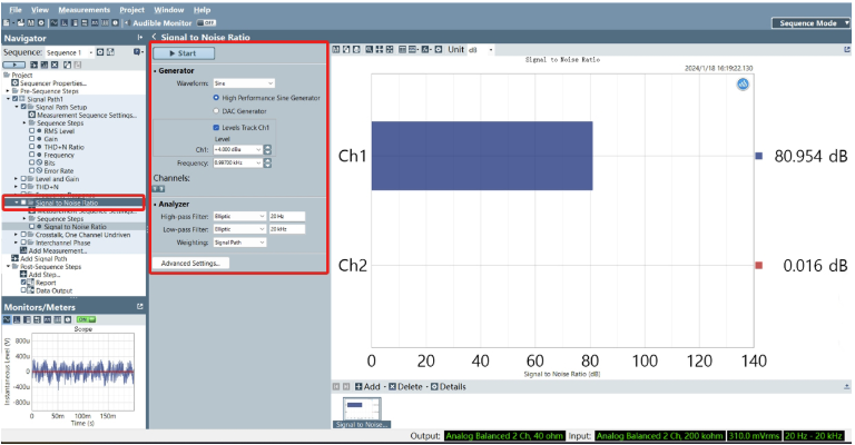
Figure 3
3.2 Amplitude-Frequency Response
Standard Measurement Method:
1)Enable the 20 Hz ~ 20 kHz bandpass filter on the test instrument's input.
2)Apply a sine wave test signal at 997 Hz with the reference measurement level to the input of the DUT digital mixer. Record the output level U0 as the reference level.
3)Change the test signal frequency. The frequency sampling points are specified in standard section 6.1. Record the output level U at each frequency sampling point.
Using Audio Analyzer: Use the Stepped Frequency Sweep function in the audio analyzer to complete this test. As shown in Figure 4, set the parameters according to the method requirements and click Start to obtain the curve showing level versus frequency.
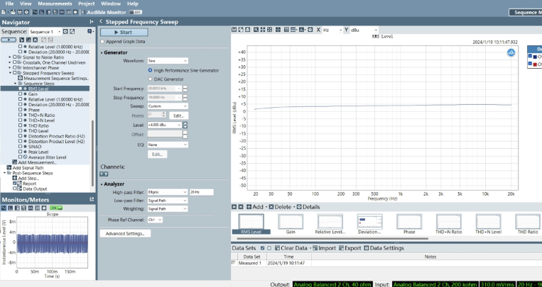
Figure 4
As shown in Figure 5, you can view a table of specific level values at different frequency points and also export the data.
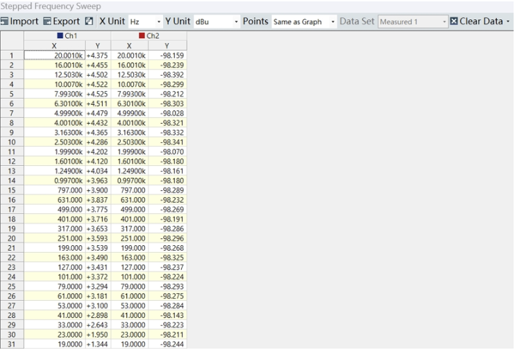
Figure 5
As shown in Figure 6, the flatness result, representing the DUT's amplitude-frequency response, can be viewed directly within this function, eliminating the need for manual calculation.
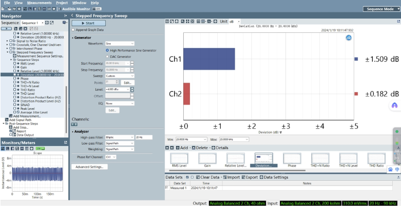
Figure 6
3.3 Total Harmonic Distortion plus Noise (THD+N)
Standard Measurement Method:
1)Enable the 20 Hz ~ 20 kHz bandpass filter on the test instrument's input.
2)Apply the reference measurement level to the input of the DUT digital mixer. The test signal frequency sampling points are specified in section 6.1. Record the output THD+N value at each frequency sampling point.
Using Audio Analyzer: THD+N can also be tested using the Stepped Frequency Sweep function. As shown in Figure 7, select THD+N Ratio in the result display. Configure the parameters according to the test method and click Start to obtain the curve showing THD+N versus frequency.
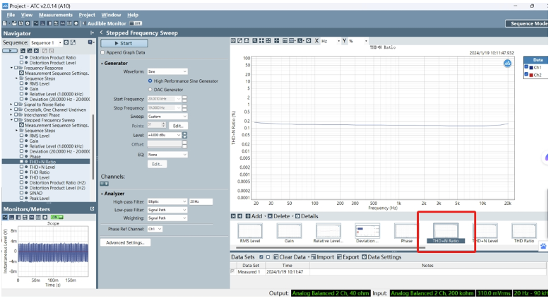
Figure 7
As shown in Figure 8, you can view a table of specific THD+N values at different frequency points and also export the data.
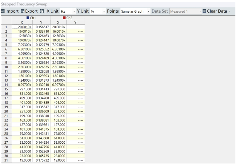
Figure 8
Signal-to-Noise Ratio (S/N), Amplitude-Frequency Response, and Total Harmonic Distortion plus Noise (THD+N) are three common test indicators. The audio analyzer can also be used to test other indicators specified in the standard. For detailed test methods, please consult Beijing Doewe Technologies Co., Ltd.