1. Introduction
ETC (Electronic Toll Collection) systems are now widely used. To ensure the stable operation of the system, testing the core components of the ETC system – the RSU (Roadside Unit) and OBU (On-Board Unit) – is crucial. The industry standard "JTG/T 3520-2021" for professional ETC system testing specifies a series of test items. This article will focus on one of these test indicators: the ETC Roadside Unit (RSU) Communication Process (hereinafter referred to as the ETC Communication Process).
The specific process of the ETC system communication is as follows: When a vehicle equipped with an OBU passes under an ETC gantry, rapid signal interaction occurs between the OBU and the RSU. Upon receiving the signal from the OBU, the system accurately reads the vehicle information and completes the toll calculation after confirmation, allowing the vehicle to pass smoothly. This article introduces ProEye, a test software provided by Beijing Doewe Technologies Co., Ltd. This software assists users in analyzing the ETC communication process, thereby improving testing efficiency.
2. Test Method & Software Introduction
2.1 Test Method
Testing the ETC communication process requires coordination with other related test equipment. The general steps are as follows:
● Use a spectrum analyzer: Set the spectrum analyzer to signal recording mode and adjust the center frequency to the required test frequency.
● Connect the receiving antenna to the spectrum analyzer. Once the signal reception is confirmed to be normal, testing can begin.
● Drive the vehicle under the ETC gantry. Simultaneously activate the signal recording function on the spectrum analyzer to record and store the signals exchanged between the OBU and RSU.
● Use the analysis software ProEye to analyze the signals and obtain the relevant information contained within them.
2.2 ProEye Software Introduction
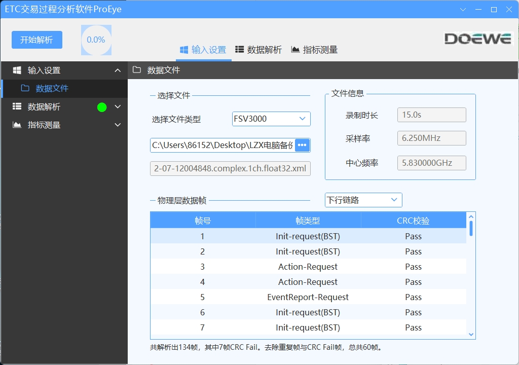
ProEye software can parse recorded RF files. It supports the analysis of RF layer metrics, application layer data, and key interactive statements and data characteristics at the device application layer. Below is an example of the software's actual testing interface.
● Import files in common formats based on the type of acquisition device for analysis.
● Analyze and identify all physical layer data frames within the recorded signal file, generating a list.
● Supports viewing detailed data frame information within the software.


● The application layer and device application layer can automatically identify key interactive statements, such as Preamble, BST, VST, SETMMI.RS, SETMMI.RQ, gantry number, license plate number, etc.
● Supports parsing relevant RF layer metrics, such as frequency, frequency tolerance, signal power, occupied bandwidth, and modulation index.


3. Software Core Advantages
● Based on relevant test standards, supports demodulation of RSU downlink signals and OBU uplink signals within recorded signal files.
● Supports testing various RF indicators, including: signal strength, carrier frequency, carrier tolerance, modulation coefficient, and occupied bandwidth.
● Supports the retrieval and judgment of key interactive statements, including: Preamble, BST, VST, SetMMI.rq, SetMMI.rs, and concatenated statements.
● Simplifies the analysis process of data primitives, intuitively presents test results, lowers the barrier to data analysis, and facilitates rapid analysis by engineers.