1. Introduction
The modulation depth of an AM (Amplitude Modulation) broadcast transmitter is one of the critical indicators for measuring its performance. It reflects the degree to which the amplitude, frequency, or phase of the carrier wave is controlled by the low-frequency modulating signal. The calculation formula for modulation depth is the ratio of the amplitude of the modulating wave to the amplitude of the carrier wave. In practical applications, the level of modulation depth directly impacts signal transmission quality and reception effectiveness.
According to national and industry standards, specific requirements exist for the modulation depth of AM broadcast transmitters. For example, per the Broadcasting, Film, and Television Industry Standard of the People's Republic of China, GY/T 225-2007 "Technical Requirements and Measurement Methods for Medium and Short Wave AM Broadcast Transmitters," any equivalent measurement method ensuring the same measurement uncertainty may also be used. This standard applies to the production, acceptance testing, operation, and maintenance of medium-wave (MW) and short-wave (SW) AM broadcast transmitters with a rated power of 1 kW and above.
When practically measuring the modulation depth of an AM transmitter, specialized modulation analyzers can be used, such as our company's RWC2500A Plus. These instruments typically possess the necessary frequency range, deviation range, sufficient signal-to-noise ratio (SNR), and frequency response to ensure measurement accuracy.
In summary, the modulation depth of an AM broadcast transmitter is a key parameter for its transmission performance. Relevant national and industry standards must be followed during design, testing, and maintenance to ensure broadcast signal quality and stability.
2. Common Problems
1、Unstable Modulation Depth: Instability may be caused by fluctuations in the transmitter's modulation circuit or power supply. Solutions include checking components in the modulation circuit for aging or damage and performing necessary replacements. Simultaneously, ensure power supply stability, potentially requiring the use of voltage regulators or UPS systems.
2、Insufficient Measurement Equipment Precision: Using measurement equipment with inadequate precision can lead to inaccurate test results. High-precision measurement equipment compliant with industry standards, such as the RWC2500A Plus, should be used.
3、Operational Complexity: FMAB, one of the representative devices in the current industry, is decades old and has been out of production for over ten years. Our RWC2500A Plus, designed specifically for AM/FM broadcast testing, with its excellent performance and modern visual operation interface, can completely replace FMAB.
4、Environmental Factor Influence: Ambient temperature, humidity, and power supply fluctuations can affect test results. Ensure the testing environment meets the specified operating conditions for the equipment.
5、Equipment Aging: Over time, aging of both the transmitter and test equipment can lead to performance degradation. Regular maintenance and calibration of equipment, along with timely upgrades, are key to maintaining testing accuracy.
When addressing these problems, relevant industry standards such as GY/T 225-2007 "Technical Requirements and Measurement Methods for Medium and Short Wave AM Broadcast Transmitters" can be referenced to ensure testing methods and equipment comply with industry specifications. Additionally, theoretical articles on AM modulation/demodulation on platforms like CSDN can be consulted to deepen understanding of AM signals and the testing process.
3. Measurement Method
The core equipment used for the measurement method described in this article is the RWC2500A Plus. For specific device information, please visit www.doewe.com.
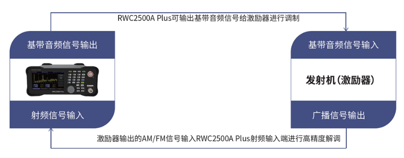
3.1 Equipment Connection
3.2 Test Procedure
The RWC2500A Plus features a modulation analysis module, an audio analysis module, and a baseband audio signal output module. To measure modulation depth, we use the baseband audio signal output module. The baseband audio signal is input into the transmitter's audio input port. After the transmitter is modulated for broadcast, connect its output (via a dummy load and a TEST signal tap) to the RF input interface of the RWC2500A Plus. Use the modulation analysis module for analysis.
3.2.1 Baseband Audio Signal Generation
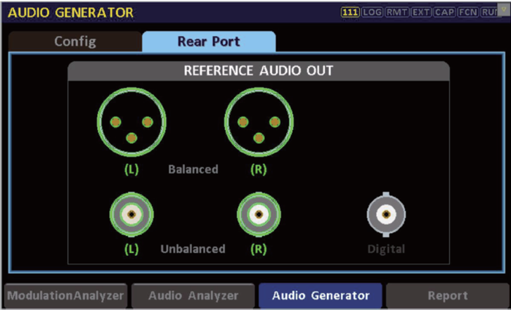
1、When using the RWC2500A Plus's baseband audio signal generator module, first select the "Rear Port" in the Audio Generator interface. In this interface, you can quickly adjust the required audio output interface (Balanced/Unbalanced/Digital). After selection, proceed to the next step.
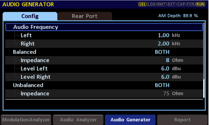
2、In this step, the user can adjust the audio signal level and frequency. For modulation depth testing, a 1 kHz audio signal is generally used. After setting the frequency, adjust the audio level on this interface. Simultaneously observe the "AM Depth" value in the upper right corner to see if the current modulation depth reaches above 90%.
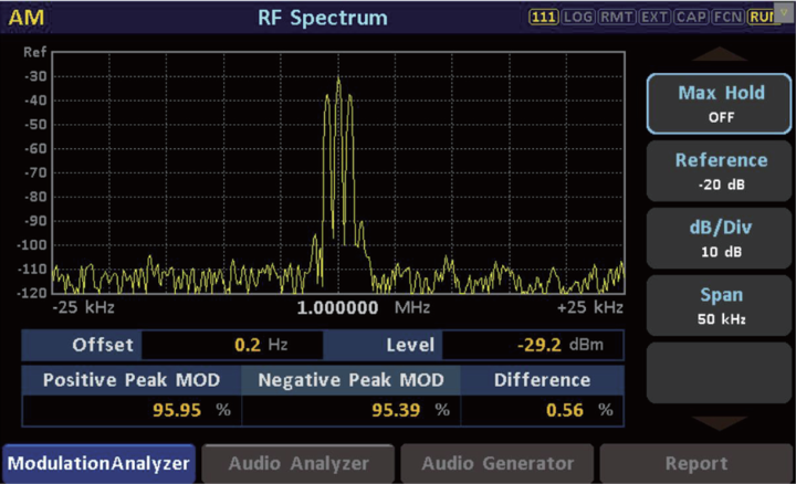
3.2.2 Modulation Analysis: AM Modulation Depth Reading
After setting the baseband audio signal input to the transmitter, the AM modulation depth and positive/negative modulation levels can be viewed directly in the RF Spectrum display of the Modulation Analyzer interface. It can also be read directly within the audio generator module.
4. Core Equipment: RWC2500A Plus
4.1 Functional Overview
The RWC2500A Plus is a professional broadcast modulation analyzer primarily used for AM/FM transmitter testing. It can comprehensively test RF parameters, modulation performance, and audio aspects as a single instrument.
The device can demodulate AM/FM (mono and stereo) with high precision in real-time, testing parameters such as carrier power, frequency error, AM modulation depth, FM frequency deviation, and pilot signal related parameters. It supports real-time output of the demodulated audio signal. The device can be configured for audio generation, outputting baseband audio signals with independent level and frequency settings for left and right channels. It features both digital (AES/EBU) and analog (balanced & unbalanced) audio output interfaces. The device includes audio analysis capabilities, analyzing the demodulated baseband audio signal, supporting frequency and time domain analysis to display audio spectrum and waveforms.
Based on its multifunctional combination, the RWC2500A Plus can directly analyze key broadcast transmitter indicators such as: carrier parameters, audio distortion, audio signal-to-noise ratio (SNR), audio frequency response, and stereo audio separation. A single instrument fulfills transmitter index testing requirements, meeting the complete testing needs for broadcast transmitters in the radio and television industry.
4.2 Product Features
● Supports high-precision AM/FM demodulation and parameter analysis, including stereo FM.
● Completely replaces the industry classic product FMAB.
● Local oscillator frequency accuracy up to 1 ppb, SNR > 80 dB.
● Demodulates and outputs baseband audio, supporting Balanced/Unbalanced/Digital interfaces.
● Displays RF spectrum, demodulated audio spectrum, and waveforms in real-time.
● Supports audio analysis, measuring distortion, SNR, frequency response, and separation.
● Supports audio generation, outputting tone or sweep signals via multiple interfaces.
● Supports custom test item upper/lower limits with real-time alerts for out-of-limit indicators.
● Supports test result overview and data export, generating reports with one click.
● Color touchscreen and button co-operative operation.
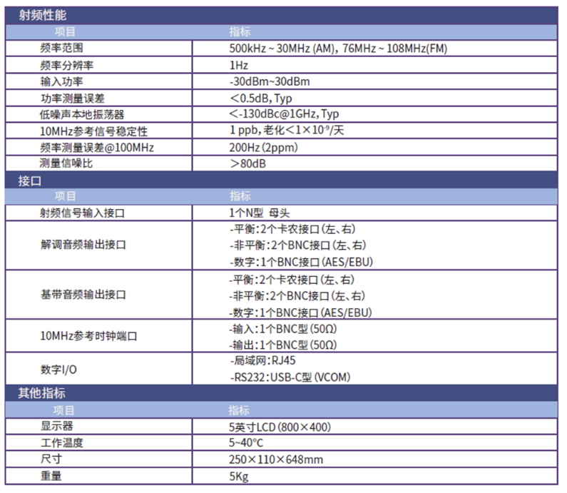
4.3 Performance Specifications