1. Introduction
As third-generation broadcasting technologies, DAB and DRM digital radio are now widely used in over 20 different countries or regions. Applications based on this technology are diverse, with in-car radio being one of the most typical scenarios. As the world's largest automobile exporter, China's demand for research and testing of this technology is also increasing daily.
In practical applications of in-car radio, a common issue arises: when a user travels from one service area to another, they may experience an interruption in listening due to leaving the coverage area of the original signal. To avoid this problem, replacement services available in the user's current area are utilized to ensure continuity of listening. This application is called Service Following.
In digital broadcasting, Service Following is achieved through Alternate Frequencies (AF) and Service Linking between the three modulation types: DAB, DRM, and FM. This article presents a test solution using Redwood Comm's broadcast signal generator RWC2010C, emergency broadcast tester RWC2100F, and the core functional software "Service Linking test tool".
Figure 1: Schematic Diagram of Service Following Function
2. Actual Service Following Interaction Process
The actual Service Following interaction process, shown in Figure 2, is divided into three stages.
Figure 2: Service Following Flowchart
Stage One:
Attempt to find a DAB service with the same Service Identifier (SId) within other ensemble signals in the current region. It is necessary to identify all DAB ensemble signals carrying service information "identical" to the current program. The receiver will also only return ensemble signals carrying the same service (i.e., same ECC and SId) as the user-selected service. In this stage, priority should be given to the ensemble frequency transmitting the service identical to the user's originally selected service.
Stage Two:
Search the database for given hard-linked services. Hard-linked services carry the same audio content as the user's originally selected service. The receiver under test (RUT) first establishes a DAB linkage set based on the service linking information and attempts to identify services within that set that have a hard link to the selected service. Ideally, a suitable candidate service is identified and monitored during this stage; once its suitability is confirmed, a change to that service can be allowed.
Stage Three:
Search the database for related soft-linked services. The process in this stage is identical to Stage Two. However, since soft-linked services are only related to the user-selected service and do not carry the same audio content, user manual intervention may be required when deciding whether to switch services.
These three stages are executed sequentially in a loop. If one stage fails, the process automatically proceeds to the next stage until the required signal is successfully acquired in one of the stages, after which it returns to the normal listening process.
3. Test Solution Introduction
The test solution provided by our company is based on the actual interaction process described in Section 2, testing the receiver under test (RUT) by simulating the entire flow. The general test method is as follows:
First, prepare the hardware connection. Connect a control PC to three RWC2010C units and one RWC2100F unit using an Ethernet cable and a switch (referred to as Device 1, Device 2, Device 3 for the RWC2010Cs, and Device 4 for the RWC2100F). Confirm the connection status of the devices on the control software. Combine the output signals from the four devices using a combiner and feed them into the car audio system under test.
Figure 3: Hardware Connection Schematic
This test setup can simulate various real-world application scenarios. Examples are provided below.
Scenario 1: Simulating switching from the original DAB ensemble signal to another DAB ensemble signal
1、Device 1 emits a DAB ensemble signal at -10 dB. Device 2 emits the same DAB ensemble signal at -120 dB. The RUT listens to the program in Device 1's signal.
2、Import a specific file into the Power Configurator to control Device 1's signal power to gradually decrease to -120 dB, and Device 2's signal power to gradually increase to -10 dB. This simulates the receiver moving from one service area to another.
3、Determine if the RUT's function is normal based on whether it successfully switches to the signal emitted by Device 2.
Scenario 2: Simulating switching from the original DAB service to an FM service
1、Device 1 emits a DAB signal at -10 dB. Device 4 is set to emit an FM signal with the same service content. The RUT listens to the program in Device 1's signal.
2、Import a specific file into the Power Configurator to control Device 1's signal power to gradually decrease to -120 dB, and Device 4's signal power to gradually increase from off (or low) to 0 dB. This simulates the receiver moving from one service area to another.
3、Determine if the RUT's function is normal based on whether it successfully switches to the signal emitted by Device 4.
Scenario 3: Simulating switching from the original DAB service to a DRM service
1、Device 1 emits a DAB ensemble signal at -10 dB. Device 3 emits a DRM signal containing the same service at -120 dB. The RUT listens to the program in Device 1's signal.
2、Import a specific file into the Power Configurator to control Device 1's signal power to gradually decrease to -120 dB, and Device 3's signal power to gradually increase to -10 dB. This simulates the receiver moving from one service area to another.
3、Determine if the RUT's function is normal based on whether it successfully switches to the signal emitted by Device 3.
Furthermore, this test solution can simulate more complex scenarios to meet diverse customer testing requirements.
4. Software Module Introduction
The software, based on its GUI mode, can be divided into three modules: Station Settings, AF Parameter Display Window, and Power Configurator.
Figure 4: Software Display Interface
① Station Settings
After connecting the application to each device via Ethernet, the connection status of the devices can be viewed in this module. Each device has 3 switches. The function controlled by the switches varies depending on the connected device or transmission mode. When connected to an RWC2010C in DAB or DRM mode, the switches represent 3 services within the ensemble signal; each service can be turned on or off individually. When connected to an RWC2100F, the switches represent 3 FM transmitters.Notably, an RWC2010C in DAB mode can provide up to 64 services per ensemble, and in DRM mode, one multiplex can accommodate 4 services. For ease of testing, the software configures only 3 services. Additionally, the parameters and attributes displayed in the software will differ depending on the connected device.
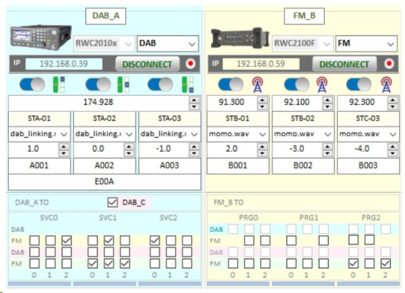
Figure 5: Station Settings Interface
② AF Parameter Display Window
The AF Parameter Display Window automatically creates and displays all AF parameters for each device based on the connection status. The AF parameters displayed in this window cannot be edited.
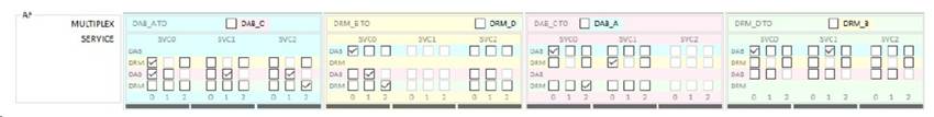
Figure 6: Example of DAB/DRM AF Link Connection
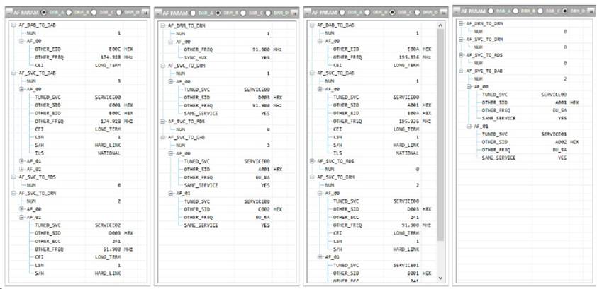
Figure 7: Example of AF Parameter Tree
③ Power Configurator
Power configuration files can be imported into the Power Configurator, or the power level of each transmitter can be set individually. This facilitates simulating various transmitter and radio broadcast signal environments that may occur in real-world situations. All power values are automatically checked and constrained based on the connected devices to ensure the instruments function correctly.
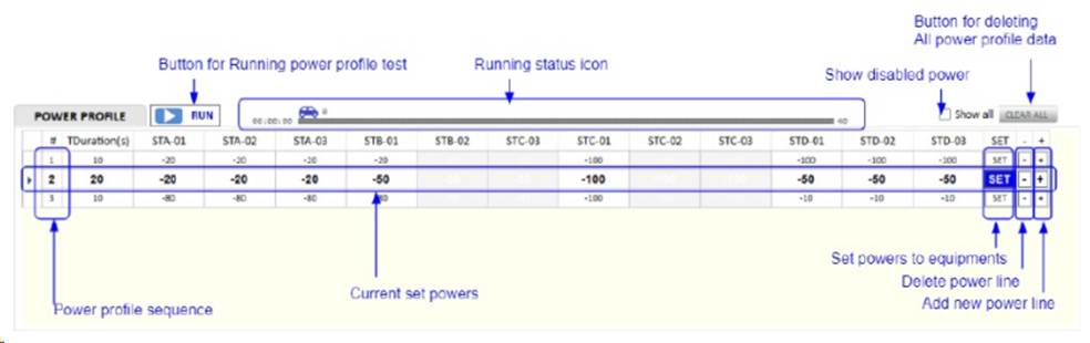
Figure 8: Power Configurator
5. Conclusion
Service Following is an application and test closely aligned with real-world scenarios. Its ultimate goal is to provide users with a better listening experience. To make the actual service more stable and reliable, it is essential to simulate real-world application scenarios as much as possible during testing. Using the RWC2010C, RWC2100F, and supporting test software provided by Doewe Technologies allows the construction of various test scenarios, effectively simulating this process for testing purposes. This provides a convenient test solution for automobile manufacturers and car audio system manufacturers. Readers interested in learning more about the products and solutions can refer to the RWC2010C and RWC2100F product brochures and related materials, or contact our company by phone (+86-10-64327909).