1. Overview
This article introduces the specific operation methods for testing in practical environments based on the testing concepts in the JTG 3520-2021 Highway Mechanical and Electrical Engineering Test Procedures standard, aiming at partial test items in the JTG 2182-2020 Highway Engineering Quality Inspection and Evaluation Standard Volume 2 Mechanical and Electrical Engineering: communication area, RSU operating signal strength, RSU operating frequency, RSU occupied bandwidth, RSU preamble, and RSU communication process.
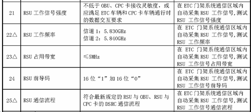
Figure 1 Partial Test Indicators of JTG 2182-2020
2. Testing Steps for Core Indicators
2.1 Communication Area Testing
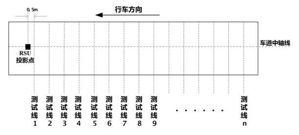
Figure 2 Schematic Diagram of Communication Area
1)First, set the range of the communication area to be tested, with the length no less than the distance from the position of the first trigger coil in the driving direction to the projection point of the RSU.
2)As shown in Figure 1, mark several test lines at equal intervals (no more than 1 meter) within the area to be tested, starting from 0.5 meters behind the projection point of the RSU.
3)Set the RSU to continuously emit the carrier; if continuous carrier emission cannot be set, testing can also be conducted in the state of continuous working signal emission.
4)Connect the test antenna to the spectrum analyzer, set the relevant test parameters on the spectrum analyzer, and switch the spectrum analyzer to the field strength testing function.
5)At the central axis position of the lane on Test Line 1, keep the test antenna at a height of 1.2 meters from the ground, slowly move the antenna to both sides of the lane, and measure the field strength of the RSU emission signal.
6)When the measured field strength drops to the specified minimum value (113 dBμV/m), record the position at this time, then move to the next test line and repeat the testing and recording using the same method.
7)The area obtained based on all recorded positions is the RSU communication area.
2.2 RSU Operating Signal Strength Testing
1)The normal output working signal of the RSU under test is used as the measured signal.
2)Connect the test antenna to the spectrum analyzer, set the relevant test parameters on the spectrum analyzer, and switch the spectrum analyzer to the channel power testing function.
3)Place the test antenna at the test position within the RSU communication area for testing.
4)Read the maximum channel power within the communication area, which is the operating signal strength of the RSU.
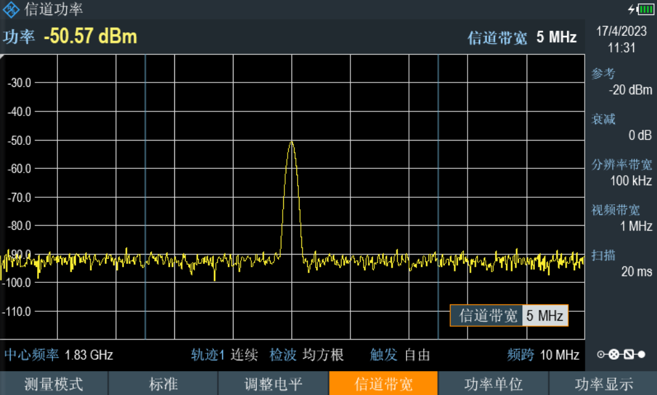
Figure 3 Channel Power Measurement Function Interface
2.3 RSU Operating Frequency Testing
1)The normal output working signal of the RSU under test is used as the measured signal.
2)Connect the test antenna to the spectrum analyzer and set the relevant test parameters on the spectrum analyzer.
3)Set an appropriate sweep width and read the frequency value at the peak of the main longitudinal mode of the signal, which is the RSU operating frequency.
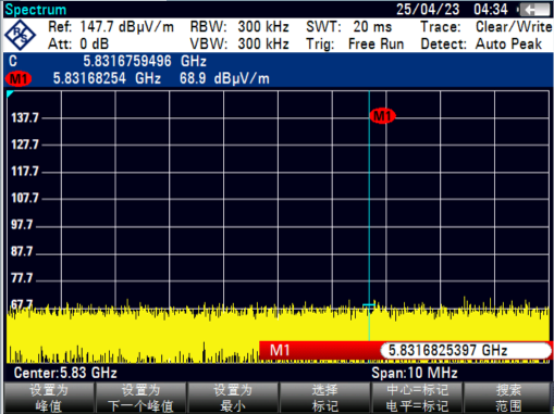
Figure 4 Schematic Diagram of Operating Frequency Testing
2.4 RSU Occupied Bandwidth Testing
1)The normal output working signal of the RSU under test is used as the measured signal.
2)Connect the test antenna to the spectrum analyzer, set the relevant test parameters on the spectrum analyzer, and switch the spectrum analyzer to the occupied bandwidth testing function.
3)Place the test antenna at the test position within the RSU communication area for testing.
4)Read the occupied bandwidth value measured by the spectrum analyzer, which is the RSU occupied bandwidth.
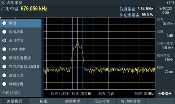
Figure 5 Occupied Bandwidth Measurement Function Interface
2.5 RSU Preamble Testing
1)Connect the test antenna to the handheld spectrum analyzer, set the relevant test parameters on the handheld spectrum analyzer, and switch it to the signal recording function.
2)Drive a vehicle equipped with a normally trading on-board unit (OBU) through the gantry under test, and use the handheld spectrum analyzer to record the complete interaction process between the OBU and RSU while passing through the gantry.
3)Analyze the information source code in the recorded signal to check whether the preamble is normal. Software can be used for auxiliary analysis, such as ProEye software developed by Beijing Doewe Technologies Co., Ltd., which can directly parse the primitive information in the signal and display the corresponding preamble.
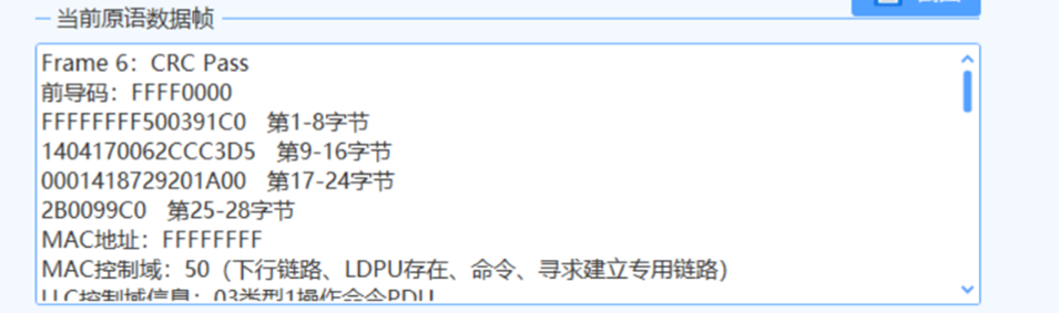
Figure 6 Primitive Data Parsing Function
2.6 RSU Communication Process Testing
1)Connect the test antenna to the handheld spectrum analyzer, set the relevant test parameters on the handheld spectrum analyzer, and switch it to the signal recording function.
2)Drive a vehicle equipped with a normally trading on-board unit (OBU) through the gantry under test, and use the handheld spectrum analyzer to record the complete interaction process between the OBU and RSU while passing through the gantry.
3)Analyze the information source code in the recorded signal, and use software for auxiliary analysis, such as ProEye software developed by Beijing Doewe Technologies Co., Ltd., which can directly parse the primitive information and other related information contained in the signal.
4)The RSU communication process test can be completed through the parsed primitives and vehicle-related information.
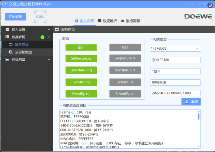
Figure 7 ProEye Software Analysis Interface
3. Typical Testing Equipment
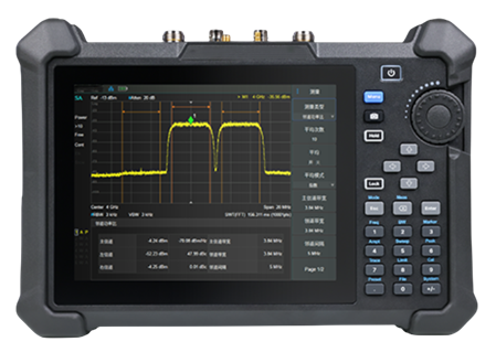
Figure 8 Handheld Spectrum Analyzer
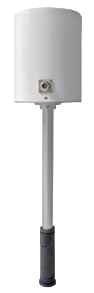
Figure 9 Omnidirectional Test Antenna
For any questions about the above testing method steps or to learn more about detailed testing solutions, please consult Beijing Doewe Technologies Co., Ltd.