1. Introduction
The ETC gantry system is a vital facility in the road traffic network. It possesses functions such as multi-path identification of passing vehicles, automatic charging, non-stop toll collection, traffic flow survey, and video surveillance, significantly improving traffic efficiency and alleviating traffic congestion. To ensure the normal operation of the ETC gantry system, its precision and accuracy are of paramount importance. Therefore, a comprehensive testing solution is required to detect and resolve potential technical issues promptly, reducing failure probabilities and enhancing ETC service quality.
Testing of the ETC gantry system is applied in various links of highway construction and maintenance, such as testing the normal operation of the ETC gantry system upon highway completion, and regular mechanical and electrical inspections and maintenance by road inspection agencies. This highlights the significance of ETC gantry system testing in ensuring the normal operation of electronic toll collection systems, improving highway management efficiency, and safeguarding road safety.
2. Core Testing Items
The testing content of Beijing Doewe Technologies Co., Ltd.'s ETC gantry system mainly focuses on Items 20-25 in Table 6.4.2 of "6.4 ETC Gantry System" in the JTG 2182-2020 Highway Engineering Quality Inspection and Evaluation Standard Volume 2 Mechanical and Electrical Engineering, including communication area, RSU operating signal strength, RSU operating frequency, RSU occupied bandwidth, RSU preamble, and RSU communication process. The specific content is as follows:
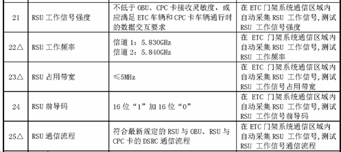
Figure 1 Measured Items of ETC Gantry System (Excerpt)
The specific testing methods mainly refer to GB/T 20851-2019 Electronic Toll Collection Dedicated Short-Range Communication and JTG 3520-2021 Highway Mechanical and Electrical Engineering Test Procedures.
3. Introduction to Testing Solution
3.1 ETC Gantry Testing System eEye
The ETC gantry testing system eEye is a set of testing systems designed specifically for the requirements of JTG 2182-2020 and JTG 3520-2021. High-precision handheld instruments are selected as core testing equipment, ensuring testing accuracy while providing high portability. Combined with dedicated customized analysis software, the testing process becomes simpler and more efficient.
3.2 Testing Methods
Based on the testing concepts in JTG 3520-2021 Highway Mechanical and Electrical Engineering Test Procedures, instruments such as field strength meters, oscilloscopes, and RF antennas are used to test the ETC gantry system. When testing the RSU operating signal strength, operating frequency, occupied bandwidth, and preamble, the testing method is conducted in a suspended traffic section. This method requires suspending vehicle traffic in the testing section, adjusting the RSU to the corresponding testing state according to specific testing items, and using field strength meters and other instruments to observe signals in the lane in real time. For testing the RSU communication process, it is not necessary to conduct the test in a closed section; simply drive through the ETC gantry and use a field strength meter to record the transaction process. As shown in Figure 2, the recorded test signals can be analyzed in a laboratory using professional transaction process analysis software to parse important information for subsequent data analysis.
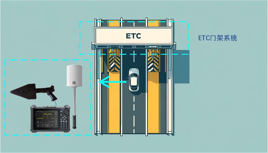
Figure 2 Schematic Diagram of Communication Process Testing
3.3 Introduction to Core Equipment & Software
3.3.1 Field Strength Meter
The field strength meter in the eEye system is a professional handheld field strength testing device with a spectrum analysis measurement range from 9kHz to 7.5GHz, covering the testing needs of the ETC gantry system. The device is compact and portable, supporting spectrum functions and various advanced measurement functions, such as occupied bandwidth testing, adjacent channel power leakage ratio testing, and channel power testing. Additionally, the device supports IQ signal collection and storage, which can be used with dedicated customized software for RSU communication process testing.
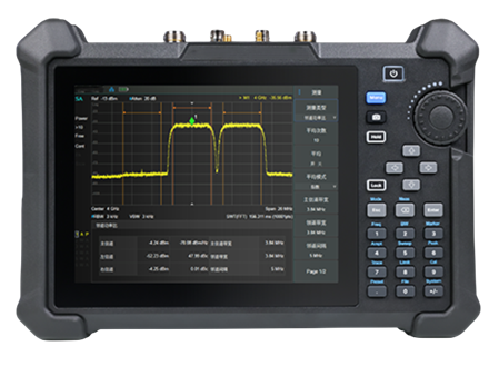
Figure 3 Field Strength Meter
3.3.2 ETC Transaction Process Analysis Software
This software in the eEye system is a professional testing software for analyzing the communication process of ETC systems. It can analyze IQ files recording the ETC RF interaction process, support common IQ file formats, and parse RF indicators including signal strength, carrier frequency, occupied bandwidth, etc., as well as application-layer indicators such as preamble, BST, VST, SetMMI.rs, SetMMI.rq, gantry number, license plate number, etc. The software enables intuitive analysis of whether the ETC system's communication process is normal.
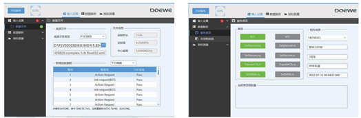
Figure 4 Software Interface Function Display
Software Advantages:
1)Simple operation: Testers can use it without complex training, improving testing efficiency while ensuring accuracy and reliability.
2)Professional analysis software allows intuitive viewing of key information in test results without parsing primitives, enhancing the readability and usability of test results.
3.3.3 Handheld Oscilloscope
The handheld oscilloscope configured in the eEye system has a bandwidth of 200MHz, a maximum sampling rate of 1GSa/s, 2 analog channels, and a storage depth of up to 12Mpts/channel. The device adopts an innovative digital trigger system with high trigger sensitivity and low trigger jitter, supports dozens of automatic measurement functions, and enables graphical statistics of measurement parameters. Equipped with a 5.6-inch capacitive touch display, it facilitates testing operations for users.
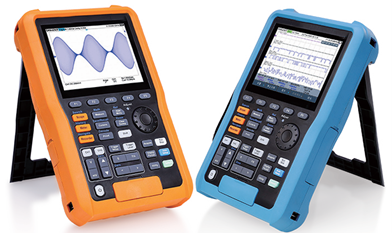
Figure 5 Handheld Oscilloscope
3.3.4 Omnidirectional & Directional Antennas
The eEye system is equipped with both omnidirectional and directional antennas. The omnidirectional antenna operates in the frequency range of 1.0 GHz to 8.0 GHz. The directional antenna, depending on the installed module, can cover a frequency range of 9 kHz to 8 GHz. Utilizing these two different antenna types meets the complex requirements of ETC gantry system testing.
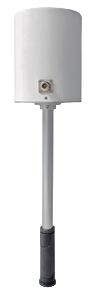
Figure 6 Omnidirectional Antenna

Figure 7 Directional Antenna
Combining the above equipment, the ETC Gantry Test System eEye brings significant convenience and efficiency improvements to ETC gantry system testing, thanks to its portability, simplified operational procedures, signal recording and re-analysis capability, and professional, intuitive test result analysis software. These advantages make testing work more flexible, efficient, and accurate, providing strong support for the stable operation of the ETC system.