1.Introduction
Carrier Shift is one of the core performance indicators of AM (Amplitude Modulation) broadcast transmitters. It is primarily used to evaluate the carrier output stability of equipment under full modulation conditions. Its physical essence is the relative attenuation ratio (unit: percentage %) of the carrier amplitude between the unmodulated state and the 100% modulation state (standard 1kHz audio modulation signal) when the transmitter operates at rated power. This indicator directly relates to the consistency and reliability of broadcast signal transmission—excellent Carrier Shift performance ensures that the transmitter maintains stable carrier output intensity during high-load modulation, allowing receivers to demodulate clear and coherent audio signals; abnormal Carrier Shift values can cause signal demodulation distortion, coverage range fluctuations, increased noise, and other issues, severely affecting the listener's reception experience.
In production quality inspection, daily operation and maintenance, and compliance verification within the broadcasting industry, the testing methods and performance evaluation of Carrier Shift strictly follow the standard "GY/T 225-2007 Technical Requirements and Measurement Methods for Medium and Short Wave AM Broadcast Transmitters." This standard clearly defines the definition and calculation formula of Carrier Shift, and establishes grading requirements through the mandatory related indicator "Carrier Output Power Change": Class A transmitters ≤±3%, Class B ≤±4%, Class C ≤±6%. These grading standards serve as the legal basis for transmitter performance determination and compliance review, providing core technical support for regulating broadcast frequency signal order and avoiding interference between devices.
The key prerequisite for accurately measuring Carrier Shift is selecting high-performance test equipment that meets standard requirements. Common test instruments often suffer from insufficient frequency accuracy and large modulation analysis errors, which can easily cause distortion in carrier amplitude measurement and affect the credibility of results. The RWC2500A Plus Broadcast Modulation Analyzer, with its 1ppb local oscillator frequency accuracy, can precisely capture the subtle differences in carrier amplitude between unmodulated and fully modulated states, avoiding systematic errors introduced by test equipment from the source; simultaneously, the device covers a working frequency range of 500kHz~30MHz (AM), perfectly adapting to test scenarios for medium and short wave AM transmitters of 1kW and above, and is fully compatible with the measurement procedures and technical requirements in the "GY/T 225-2007" standard, providing stable and reliable technical support for accurate detection of Carrier Shift indicators.
2. Core Calculation Formulas and Main Influencing Factors
2.1 Interpretation of Core Calculation Formulas
2.1.1 Basic Formula (When Power Supply is Stable)
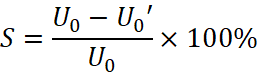
Description: U0 is the carrier amplitude without modulation, U0′ is the carrier amplitude at 100% modulation (standard 1kHz audio signal). This directly calculates the relative attenuation ratio between the two, intuitively reflecting the carrier stability during the modulation process.
2.1.2 Correction Formula (When Power Supply Fluctuates)
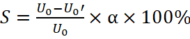
Description: (U1is the effective value of power supply voltage without modulation, U1′is the effective value of power supply voltage at 100% modulation). This is used to compensate for measurement errors caused by grid voltage fluctuations (exceeding ±2%), ensuring the results reflect the true performance of the transmitter.
2.2 Main Influencing Factors
1.Power Supply System: Excessive internal resistance in high-voltage rectifier devices, rectifier transformers, and filter chokes can cause the power supply voltage to the amplifier tubes to drop when the transmitter operating current increases at 100% modulation; insufficient filter capacitor capacity and inadequate filtering stages lead to increased power supply output ripple, intensifying voltage fluctuations during modulation, both of which cause carrier amplitude attenuation.
2. Amplification Stage: Unreasonable operating point settings for final-stage amplifier tubes (excessive or insufficient static current) can easily drive them into nonlinear operating regions during full modulation, unable to maintain stable carrier output; aging of amplifier tubes after long-term use and reduced transconductance lead to decreased current output capability during full-load modulation, directly causing carrier amplitude attenuation.
3. Load Matching: Deviation of the transmitter output load and antenna system impedance from the standard 50Ω value can cause power reflection back to the amplification stage, disrupting amplification stage operating stability; parameter drift in inductors and capacitors within the matching network causes load impedance to vary with modulation frequency, further amplifying the Carrier Shift phenomenon.
4.Environment and Power Supply: Strong electromagnetic interference generated by frequency converters and high-voltage equipment in the test environment can superimpose on the carrier signal, causing amplitude measurement distortion; sudden grid voltage rises or drops and three-phase voltage imbalance can directly transfer to the transmitter power input, causing abnormal carrier amplitude fluctuations and affecting measurement accuracy.
3.Measurement Methods
The Carrier Shift measurement diagram in the standard "GY/T 225-2007" is shown below. The core equipment used in the measurement methods described in this article is the RWC2500A Plus. For specific device information, please visitwww.doewe.com。
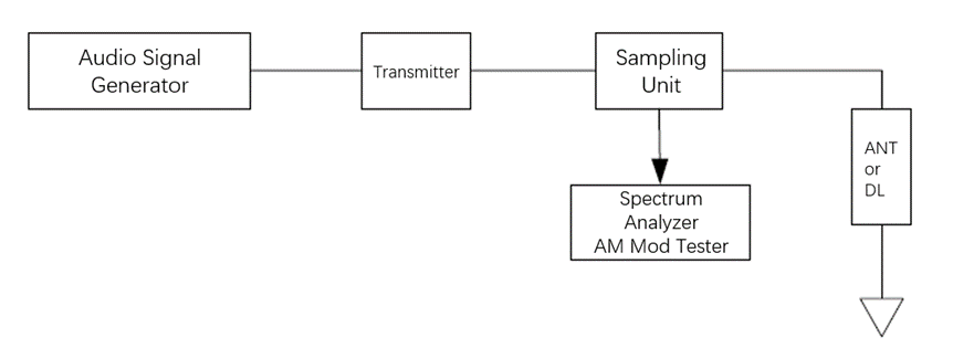
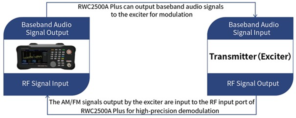
3.1 Equipment Connection
3.2 Test Procedure
The RWC2500A Plus features a modulation analysis module, audio analysis module, and baseband audio signal output module. When measuring signal-to-noise ratio, we need to use the baseband audio signal output module to input the baseband audio signal into the transmitter's audio input port. After the transmitter is modulated and broadcast, connect the load and TEST signal to the RWC2500A Plus RF signal input interface, and use the modulation analysis module for analysis. Before testing, press the FREQ button to set the center frequency, ensuring the RWC2500A Plus frequency matches the transmitter frequency.
3.2.1Baseband Audio Signal Generation
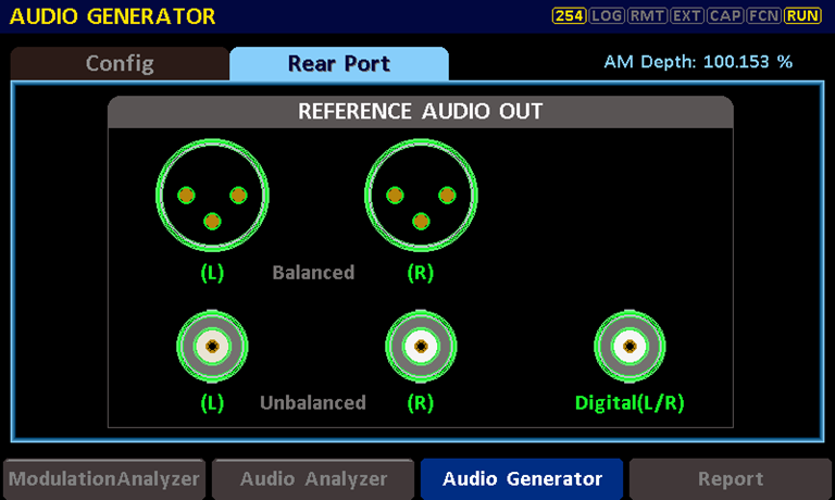
- When using the RWC2500A Plus baseband audio signal generation module, first select "Rear Port" in the Audio Generator interface. In this interface, you can quickly adjust the required audio output interface (Balanced/Unbalanced/Digital). After selection, proceed to the next step.
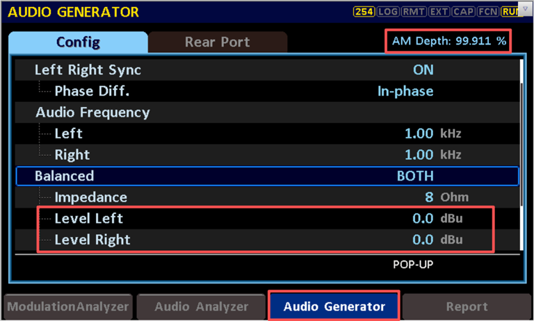
2.In this step, users can adjust the level and frequency of the audio signal. When testing Carrier Shift, generally use a 1kHz audio signal. After setting the frequency, you can adjust the audio level size in this interface. While adjusting, observe the upper right corner to ensure AM Depth is around 100% in AM mode.
3.2.2Modulation Analysis
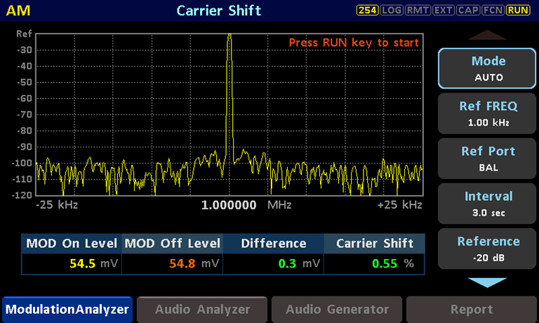
1. In the Modulation Analyzer pull-up menu, enter the Carrier Shift interface. Set the Mode on the right side to AUTO, Ref FREQ to 1kHz, and Ref Port to UNBAL/BAL/DIG according to the connection interface. Press RUN in the right button area, wait a few seconds, and then read the Carrier Shift value in the Carrier Shift column.
4.Core Equipment: RWC2500A Plus
4.1 Functional Overview
The RWC2500A Plus is a professional broadcast modulation analyzer primarily used for AM/FM transmitter testing, capable of single-unit comprehensive testing of RF parameters, modulation performance, and audio-level metrics.
The device can demodulate AM/FM (mono and stereo) in real-time, measuring carrier power, frequency deviation, AM modulation depth, FM frequency deviation, and pilot signal-related parameters. The device supports real-time output of demodulated audio signals. It features audio generation functionality that can output baseband audio signals, supporting independent settings for left/right channel levels and frequencies, with digital (balanced) and analog (balanced/unbalanced) audio output interfaces. The device has audio analysis capabilities to analyze demodulated baseband audio signals, supporting frequency-domain and time-domain analysis to display audio spectrum and waveform.
The RWC2500A Plus can directly analyze key broadcast transmitter metrics such as carrier parameters, audio distortion, audio SNR, audio frequency response, and stereo audio separation through its multifunctional combination, achieving transmitter metric testing with a single instrument to meet broadcasting industry transmitter testing requirements.
4.2 Product Features
• Supports high-precision AM/FM demodulation and parameter analysis, including stereo FM
• Fully replaces the industry-standard FMAB product
• Local oscillator frequency accuracy up to 1ppb, SNR: AM: 70dB (Typ.), FM: 75dB (Typ.)
• Can demodulate and output baseband audio, supporting balanced/unbalanced/digital interfaces
• Can display RF spectrum in real-time, and spectrum/waveform of demodulated audio
• Supports audio analysis to measure distortion, SNR, frequency response, and separation
• Supports audio generation to output single-tone or sweep signals with multiple interface options
• Supports custom upper/lower limits for test items, with real-time alerts for out-of-limit metrics
• Supports test results overview and data export, one-click report generation
• Color touchscreen and button collaborative operation
4.3 Performance Specifications
RF Performance
- Frequency Range: 500kHz~30MHz (AM), 76MHz~108MHz (FM)
- Frequency Resolution: 1Hz
- Input Power: -30dBm~30dBm (Permitted), -20dBm~20dBm (Calculated)
- Power Measurement Error: <0.5dB, Typ.
- Low Noise Local Oscillator: <-130dBc@1GHz, Typ.
- 10MHz Reference Signal Stability: 1ppb, aging <1×10⁻⁹/day
- Frequency Measurement Error @100MHz: <20Hz
Audio Performance
- Reference Audio Output Frequency Range: 20Hz~20kHz
- Reference Audio THD: <0.02%
- Reference Audio Frequency Response: Max: ±0.1dB
- De-emphasis Options: 50/75µs
- Left/Right Channel Level Difference: ≤0.1dB
- Measurement SNR: AM: 70dB (Typ.), FM: 75dB (Typ.)
- Measurement Isolation: 50dB
Interfaces
- RF Signal Input Interface: 1 N-type female connector
- Demodulated Audio Output Interface:
- Balanced: 2 XLR connectors (L, R)
- Unbalanced: 2 BNC connectors (L, R)
- Digital: 1 BNC connector (AES/EBU)
- Baseband Audio Output Interface:
- Balanced: 2 XLR connectors (L, R)
- Unbalanced: 2 BNC connectors (L, R)
- Digital: 1 BNC connector (AES/EBU)
- 10MHz Reference Clock Port:
- Input: 1 BNC type (50Ω)
- Output: 1 BNC type (50Ω)
- Digital I/O:
- LAN: RJ45
- RS232: USB-C type (VCOM)
Other Specifications
- Display: 5-inch LCD (800×400)
- Operating Temperature: 5~40°C
- Dimensions: 250×110×348mm
- Weight: 5kg