1. Introduction to RDS
According to the Chinese standard (GB4311.3-84), the frequency range for FM broadcasting in China is 87.5~108 MHz. To prevent interference between FM stations, the channel spacing between stations is stipulated as 200 kHz, with a maximum frequency deviation of 75 kHz and a maximum modulation frequency of 15 kHz. Consequently, the theoretical bandwidth of the baseband signal for FM stereo broadcasting is 53 kHz, while that for FM monaural broadcasting is 15 kHz. Therefore, within the FM broadcast band, the frequency range from 53-100 kHz or 5-100 kHz is largely unused. This allows for the extension of multiple sub-channels within each FM channel, enabling not only the transmission of multiple programs but also the transmission of data and other information. This approach fully utilizes frequency resources and technical equipment. These technologies are collectively referred to as FM Multiplexing Technology (Multi-program Broadcasting, SCA, RDS). The frequency distribution is illustrated in Figure 1.
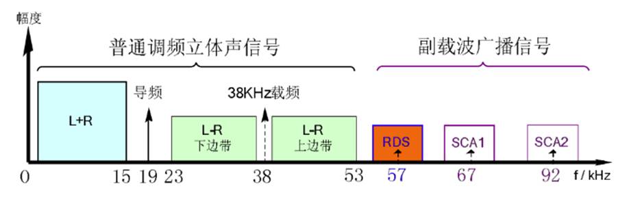
Figure 1: FM Multiplex Broadcasting Spectrum Distribution
Among these, RDS (Radio Data System) is a technical standard (EBU 3244) proposed by the European Broadcasting Union (EBU) in 1984. This technology makes full use of the existing FM broadcast bandwidth without requiring dedicated bandwidth allocation. A 57 kHz subcarrier data signal is superimposed onto the FM program band, allowing digital signals to be received alongside the audio signal. The data content includes station name, program type, traffic information, standard time, advertising information, etc. The commonly used RDS mode today generally refers to this method of carrying data via the FM broadcast subcarrier, as shown in Figure 2.

Figure 2: RDS Transmission System Composition
RDS Hardware Specifications:
Subcarrier Pilot: 57 kHz ± 6 Hz; nominal deviation on the main carrier: ±1.0 kHz to ±7.5 kHz.
Modulation Method: PSK (Phase Shift Keying).
Data Transmission Bit Rate: 1187.5 bits/s.
2. RDS Data Format
RDS data signal transmission uses a group as the basic unit. One valid data acquisition requires at least one complete data frame. A frame consists of 4 data blocks. Each data block contains 26 bits: the high 16 bits are the information code, and the low 10 bits are the check code and the data block identifier (offset value). The data transmission bit rate is 1187.5 Hz. Therefore, one frame contains 104 bits, with a transmission time of approximately 87.6 ms. This translates to 148 bytes of information transmitted per second. Excluding redundant information, the effective payload is 92 bytes.
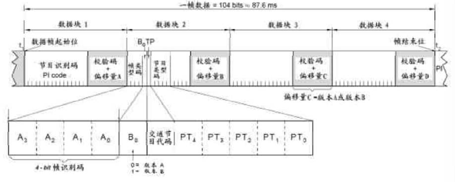
Figure 3: RDS Frame Data Format
3. RDS Data Reception and Processing
RDS receiver hardware primarily includes a microprocessor, frequency synthesizer tuner, power supply, power amplifier, and speaker. The tuner is responsible for receiving the radio signal, as shown in Figure 4.
The RDS decoder receives the PSK data stream. The microprocessor parses the RDS data stream and controls the receiver's frequency synthesizer circuit. The human-machine interface (HMI) uses an LCD or VFD display to show station content, local time, RDS playback information, etc.
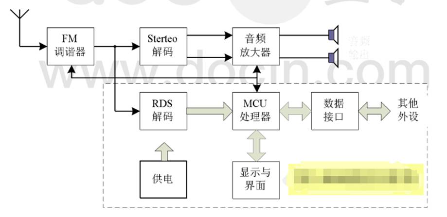
Figure 4: RDS Receiver Block Diagram
Several companies have developed RDS receiver/decoder chips, such as PT2579S, SAA6588, and the fully integrated SI47XX series. After performing data demodulation and channel decoding/error correction, the receiver chip outputs data via SPI. To promptly respond to the data arriving from the RDS demodulator's SPI interface, the microcontroller unit (MCU) digital signal processing unit employs an external interrupt method to capture data. RCLK is connected to an external interrupt input pin triggered by the rising edge, and RDATA is connected to a general-purpose I/O pin of the MCU. Note that the clock period is 842 µs. The time spent processing data within the interrupt service routine (ISR) after each data capture must not be too long; it is best kept within 200 µs to 300 µs.
As seen in the frame data structure in Figure 3, the transmission sequence of a complete frame is Block 1, Block 2, Block 3, Block 4. Within each block, the 26 bits are transmitted with the Most Significant Bit (MSB) first (i.e., the higher-order bits are transmitted first on the right). To receive a complete frame, Block 1 must first be used for data synchronization. The other three blocks can then be received sequentially. If an error occurs in receiving any block within the frame, the entire frame must be discarded, and synchronization must restart.
3.1 Stage 1: Block 1 Reception and Synchronization
Define a 16-bit wide data storage array R_buf[4] to hold the valid information (high 16 bits) of the 4 data blocks. Set up a 4-byte (32-bit) data reception buffer Rbuf. Its data structure is as follows:

Where D₁₅ - D₀ are the 16 information bits, X represents 6 unused bits.
C₉ - C₀ are the 10 bits containing the information data check code and block sync word.
After each interrupt receives 1 bit of data, each bit in Rbuf is logically shifted left by one position. The new data bit is stored in the least significant bit (LSB) position on the right. The data structure change is as follows:

Where Bᵢ is the newly received data bit. Note: The unused 6 bits (XXXXXX) do not participate in the shift operation.
The RCLK is a continuously output receive clock, even when no RDS data is present. Therefore, to determine if Rbuf has received a complete Block 1, a CRC check and sync word verification must be performed on Rbuf after receiving each new bit. The RDS check code generation polynomial is:
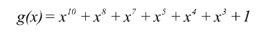
Based on this polynomial, calculate the CRC check code (Drc) for the high 16 bits of data. Perform an XOR operation between Drc and the low 10 bits of data. If the result equals the Block 1 sync word offset value A, it indicates that Block 1 has been received correctly. The high 16 bits of Rbuf constitute the valid information code for Block 1. The reception flow is shown in Figure 5.
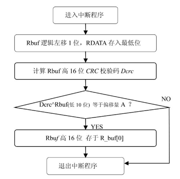
Figure 5: Block 1 Reception Program Flowchart
3.2 Reception of the Other Three Data Blocks
Once Block 1 is correctly received and synchronization is established, the other three blocks can be received using a counting method. After receiving every 26 bits, a CRC check and block sync confirmation are performed, using the same algorithm described in Section 3.1. However, the offset value A must be replaced with offset B, C, or D for the respective block. Upon correct reception of each block, it is stored in the corresponding receive buffer Rbuf. Reception continues until Block 4 is complete. To ensure data integrity, if the CRC check result indicates an error at any point, the process must revert to the Block 1 reception stage and restart synchronization.
4. Application of RDS Emergency Broadcasting Technology
RDS was first introduced in China in 1991. By 1995, the Chinese National Standard GB/T 15770-1995 "Technical Specification for Radio Data System (RDS)" was enacted, marking the beginning of RDS technology application in China. Technical solutions have been proposed for various application projects. RDS can fully transcend the limitations of traffic broadcasting and become another vital channel for information dissemination in the modern information society. In recent years, China has developed various application systems utilizing RDS, with promising prospects in fields such as: Intelligent Transportation Systems (ITS), Agricultural Disaster Prevention and Mitigation, Government Public Information Dissemination, Fixed and Mobile Vehicle Advertising, "Village Broadcasting" systems under the "New Rural Development" initiative, Education, Meteorological Information Distribution.
Natural Disaster and Meteorological Early Warning Information Dissemination Systems: Leveraging existing FM radio stations or cable television systems across regions, coupled with RDS encoders, enables both wireless early warning information dissemination and simultaneous cable transmission. This multi-channel, multi-path approach solves the challenge of rapid early warning dissemination. In large-scale national or provincial-level early warning dissemination systems, RDS's automatic information identification capability can automatically locate warning channels and retrieve warning messages. This holds significant importance in disaster prevention, mitigation, and the building of a harmonious society.