1. Overview of DSRC Systems
The DSRC communication protocol is a vital component of the ITS (Intelligent Transportation Systems) standards framework and serves as the foundation for the entire intelligent transportation service system. A DSRC system is a wireless mobile communication system that organically integrates vehicles and roads through bidirectional data transmission. Utilizing computer networks, it provides high-speed wireless communication services for information exchange between vehicles (V2V) and between vehicles and infrastructure (V2I) within ITS. DSRC systems can support public safety between moving vehicles and enable Electronic Toll Collection (ETC), offering high-speed data transmission while ensuring low latency and low interference in communication links, thereby guaranteeing the reliability of the entire transportation system.
2. Components of a DSRC System
Dedicated Short Range Communication equipment, based on the DSRC specification, primarily consists of two parts: the Road Side Unit (RSU) and the On-Board Unit (OBU). Information exchange between the road network and vehicles is achieved through wireless communication between the RSU and OBU. DSRC is a short-range wireless communication system that acts as a vehicle-road communication platform, organically connecting vehicles and roads through bidirectional information transmission.
Typical application environments (communication zones) for a dedicated short-range communication system are shown in Figure 1 and Figure 2.
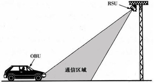
Figure 1 Communication Zone of a Typical DSRC System (Side View)
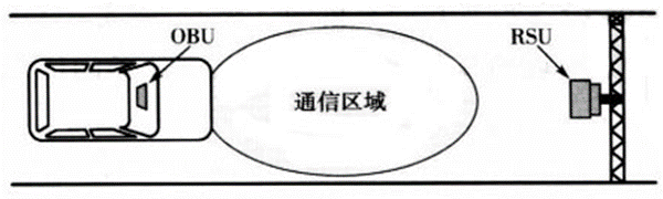
Figure 2 Communication Zone of a Typical DSRC System (Top View)
The RSU acts as the read/write controller for the OBU. Composed of encryption circuits, encoder/decoder circuits, and a microwave communication controller, it enables secure and reliable information exchange between the mobile OBU and the RSU using the DSRC communication protocol for data exchange and microwave wireless transmission.
The OBU is a mobile identification device with microwave communication and information storage capabilities. The OBU itself can function as an independent data carrier as a single-unit electronic tag. Alternatively, by adding a smart card read/write interface, it can achieve extended data storage, processing, and access control functions, becoming a dual-unit electronic tag. The introduction of a smart card not only significantly increases the extended storage space of the electronic tag, allowing for more applications, but also enables its use as a financial stored-value card in the form of an electronic wallet, greatly reducing operational risks for the system.
3. Characteristics of DSRC Systems
DSRC devices connect to computers via a universal serial port, forming a high-performance mobile data acquisition device. By configuring corresponding computer software, equipment, and networks, systems for OBU information statistics, processing, and management can be established to meet different application requirements. They are widely used in relevant short-range mobile information application fields such as toll collection for roads and bridges, public security and traffic management, intelligent communities, and customs clearance.
Based on modulation methods, DSRC systems can be categorized into two types: Active Systems and Passive Systems. Active Systems are also called Transceiver Systems. In this system, both the OBU and RSU have oscillators and can transmit electromagnetic waves. After the RSU transmits an interrogation signal to the OBU, the OBU uses its own battery power to transmit data back to the RSU. Active OBUs must therefore have batteries. Passive Systems are also known as Transponder Systems or Backscatter Systems. Here, the RSU transmits an electromagnetic signal, which activates the OBU, bringing it into a communication state. The OBU then responds by backscattering a modulated signal back to the RSU. Passive OBUs may or may not have a power source.
5.8GHz microwave DSRC, based on the HDLC (High-level Data Link Control) protocol, features area segmentation, Time Division Multiple Access (TDMA), master-slave control, and transparent transmission. These characteristics have gradually made it a communication method recognized by DSRC researchers and developers worldwide. A block diagram of the "Dedicated Short Range Communication Equipment" principle is shown in Figure 3.
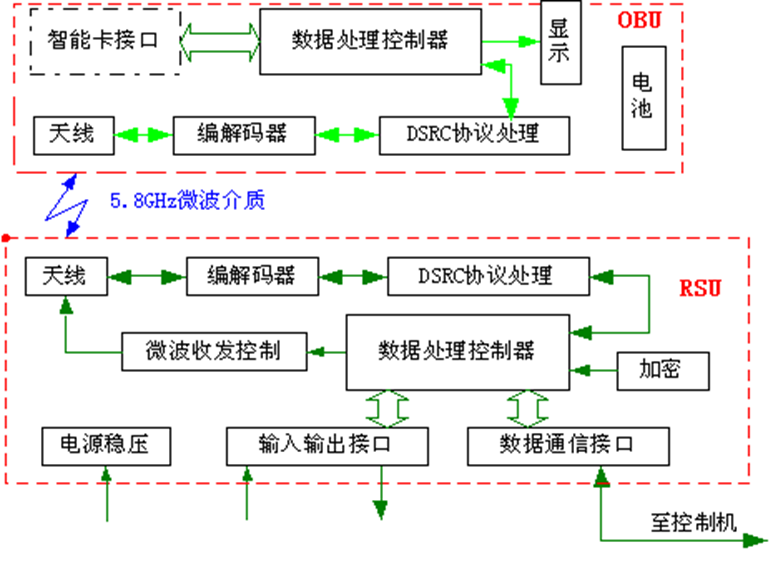
Figure 3 Schematic Diagram of DSRC Equipment
4. Overview of the DSRC Protocol
To implement intelligent, real-time, and dynamic traffic management, an international communication protocol specifically designed for ITS applications between roads and vehicles has been developed, namely the Dedicated Short Range Communication (DSRC) protocol. DSRC utilizes efficient wireless communication technology to provide an organic link between moving vehicles and the road infrastructure, enabling accurate and reliable bidirectional transmission of images, voice, and data within a small range. Compared to other wireless communication protocols, DSRC technology boasts characteristics such as high transmission rate, short transmission delay, and low implementation complexity, making it more suitable for the demanding environments of V2V and V2I communication.
5. DSRC Protocol Functions and Structure
Addressing the application requirements of DSRC equipment, the DSRC protocol architecture follows the three-layer structure of the OSI reference model: the Physical Layer, the Data Link Layer, and the Application Layer. Data transmission between layers is ensured by their respective protocols, with these three layers constituting the DSRC protocol stack. Its structure is shown in Figure 4.
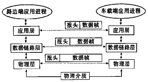
Figure 4 DSRC Protocol Architecture Diagram
Application Layer: Defines the segmentation and reassembly of application service data and provides the service interface to the application system. Data Link Layer: Enhances the raw bitstream transmission of the physical layer, ensuring error-free transmission for the upper layers. It consists of the MAC (Medium Access Control) sublayer and the LLC (Logical Link Control) sublayer. Physical Layer: Provides the physical media channel.
5.1 Functions of the MAC and LLC Sublayers
MAC Sublayer: Establishes the communication connection between the RSU and OBU via the physical media channel. It handles time slot allocation, data unit segmentation and reassembly, and related acknowledgment operations.
LLC Sublayer: Defines the transmission and error control of LLC Protocol Data Units (LPDUs) over the wireless link between the RSU and OBU. The LLC sublayer generates Command PDUs and Response PDUs for transmission and interprets received Command and Response PDUs.
5.2 Application Layer
The Application Layer comprises three core Kernel Elements (KEs):
Initialization Kernel Element (I-KE): Responsible for establishing communication initialization between the OBU and RSU.
Broadcast Kernel Element (B-KE): Utilizes broadcast data concentration areas in the OBU and RSU to collect, broadcast, and publish information related to different applications.
Transfer Kernel Element (T-KE): Responsible for the transmission of information between peer service users on both communication sides.
The structure of the Application Layer Kernel Elements is shown in Figure 5.
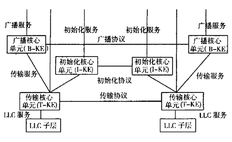
Figure 5 Application Layer Kernel Element Structure
Initialization Kernel Element (I-KE) is responsible for establishing communication initialization between the On-Board Unit (OBU) and Road Side Unit (RSU). Broadcast Kernel Element (B-KE) utilizes broadcast data concentration areas in both OBU and RSU to collect, broadcast, and distribute information related to different applications. Transfer Kernel Element (T-KE) handles information transmission between peer service users on both communication sides.
6. Comparison of Existing DSRC Standards
The CEN (European Committee for Standardization) DSRC standard is the result of compromise among its member states. Beyond basic stipulations for each layer, it offers many optional or configurable parameters. This approach provides maximum flexibility, but due to ambiguities in many areas, it cannot constitute a rigorous standard, potentially leading to different interpretations by manufacturers. However, the European DSRC system is designed to support different physical media, is suitable for multiple application scenarios and multi-lane environments, ensuring a broad application domain for the technology.
The Japanese standard is more rigorous compared to the CEN standard, with clearer descriptions and parameter specifications. Furthermore, the Japanese standard divides the DSRC frequency band into 7 groups, each corresponding to different applications (currently, two are designated for ETC applications). This specification helps improve channel utilization.
7. Applications of DSRC Technology in the ITS Domain
As a wireless communication method, DSRC in ETC systems offers features such as fast transmission speed (1Mbps), low susceptibility to interference (dedicated communication band at 5.8GHz), and good security (pseudo-random encryption algorithms). It flexibly links roadside infrastructure and vehicles, enabling bidirectional real-time information transmission. Based on these characteristics, DSRC finds applications in many ITS subsystems, such as: Advanced Public Transportation Systems (APTS), Commercial Vehicle Operations Systems (CVOS), Advanced Traveler Information Systems (ATIS), Advanced Traffic Management Systems (ATMS).
Currently, DSRC systems have been widely applied in various aspects of ITS, serving the following purposes:
1、Electronic Toll Collection (ETC): Uses microwave or infrared wireless read/write identification equipment to automatically identify vehicles and collect tolls without stopping on ETC lanes, reducing stopping time and improving traffic capacity. Also used for automatic timing and charging in paid parking lots, making the charging process more convenient, fast, secure, and manageable.
2、Providing Road Traffic Information: Utilizes the bidirectional interactive function of DSRC systems to provide traffic information from various locations to a traffic information center. After processing, the center provides drivers with real-time information on roads, traffic conditions, and other relevant data.
3、Vehicle Monitoring and Anti-Theft Function: Registers and records vehicle owner, model, license plate, and other related information. DSRC systems enable real-time vehicle management. By installing RSUs at major intersections and toll stations, stolen vehicles passing through can be detected.
4、Public Transport Management: Employs DI (Data Identifier) coding for operational vehicle positioning. Transmits vehicle position data to the public transport dispatch center, enabling real-time communication between operational vehicles and the command center. Optimizes vehicle scheduling and management based on operational status information. Provides passengers with route, fare, and departure time information, and provides drivers with real-time congestion and available parking space information related to public transport. Enhances the comfort, safety, and smoothness of public transport and effectively manages public transport while collecting operational data.
5、Safe Driving Support: RSUs can detect vehicles ahead, behind, and in the surrounding area. Information such as speed and direction of nearby vehicles is processed by a management center and provided to the driver to prevent traffic accidents.
6、Special Vehicle Management and Emergency Rescue: Identifies vehicle attributes to enable dynamic management of special vehicles such as police cars, ambulances, and fire trucks. In emergencies, the DSRC system can be relied upon for real-time traffic and road condition information collection and processing, allowing emergency vehicles to reach the incident location via the fastest route in the shortest possible time.
7、Providing Traffic Data for Urban and Road Planning: By installing RSUs on road sections requiring surveys, the DSRC system can perform real-time point-specific passage recording and traffic volume statistics for different vehicle types without requiring them to stop.