I. Solution Overview
This solution focuses on ground static fire testing of rocket engines. A static fire test is usually performed on a test stand. The engine under test is fixed in place and operated for a short-duration burn. Test engineers need to synchronously record thrust output, engine surface temperature variation, and vibration response during ignition shock and the combustion stage. The ignition time can be used as a time reference to determine when thrust, temperature, and vibration changes occur.
Mature rocket test cases show that traditional standalone instruments can record one type of signal, but they often create gaps in multi-sensor synchronization, real-time display, filtering, frequency-domain analysis, and post-test indicator calculation. In particular, if thrust curves, temperature trends, and vibration spectra are scattered across different systems, engineers often need to export, align, and process data manually after the test, reducing the efficiency of test review.
Mature rocket test cases show that traditional standalone instruments can record one type of signal, but they often create gaps in multi-sensor synchronization, real-time display, filtering, frequency-domain analysis, and post-test indicator calculation. In particular, if thrust curves, temperature trends, and vibration spectra are scattered across different systems, engineers often need to export, align, and process data manually after the test, reducing the efficiency of test review.
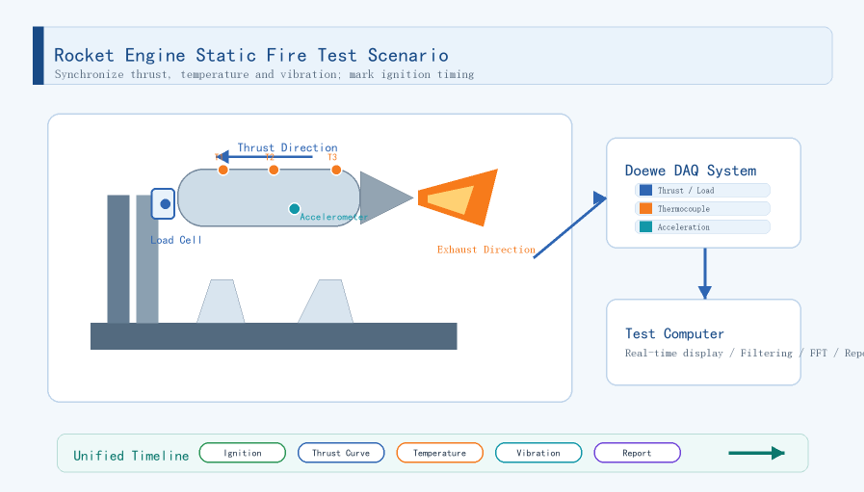
Figure 1 Rocket engine static fire test scenario
II. Test System Description
2.1 Static Fire Measurement Chain
A static fire test system typically consists of the engine under test, test stand, sensor measurement chain, data acquisition system, and test computer. The engine is installed on the stand. A thrust sensor or load cell is arranged in the load path. Thermocouples are placed along the engine axis or at key thermal response locations. Accelerometers are mounted on the engine case to record ignition shock and vibration during combustion.
In measurement planning, thrust measurement is used to obtain thrust curves, maximum thrust, burn time, total impulse, and specific impulse. Temperature measurement records temperature rise on the case, near the nozzle, and at other critical thermal response locations, including post-burn thermal behavior. Vibration measurement is used to observe time-domain waveforms, FFT spectra, and dominant frequency peaks. The ignition period is not treated as a separate acquisition channel here. Instead, it serves as a time reference during the test, helping identify the sequence in which different responses appear.
Different measurement quantities do not change at the same speed. Thrust and vibration focus more on ignition and combustion-stage dynamics, while temperature focuses more on continuous trends and thermal lag after shutdown. The Doewe solution uses a unified clock, synchronized sampling, and complete data recording so that all three signal types can be aligned on the same time axis for later review and indicator calculation.
Table 1 Typical measurement points and acquisition focus for static fire tests
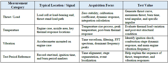
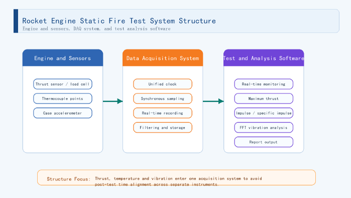
Figure 2 Rocket engine static fire test system structure
2.2 Test and Analysis Software
Doewe's test and analysis software covers channel configuration, real-time monitoring, filtering, FFT analysis, and report output. During test preparation, the software can establish measurement point lists, channel names, engineering units, sensor sensitivities, sampling strategies, and test record templates, reducing errors caused by on-site configuration.
During a static fire test, the software interface can display thrust, temperature, and vibration data at the same time. The thrust window can overlay raw and filtered curves while showing key values such as maximum thrust. The temperature window can display multi-point temperature trends and peak temperature. The vibration window can show both time-domain waveforms and frequency-domain results, helping engineers identify the main vibration frequency during combustion.
After the test, the software can generate analysis results around the key indicators of rocket static fire testing, including maximum thrust, burn time, total impulse, specific impulse, peak temperature, temperature rise process, vibration spectrum, and dominant frequency peaks. Data can also be exported according to project needs for comparison with test databases, simulation results, or records from multiple test rounds.
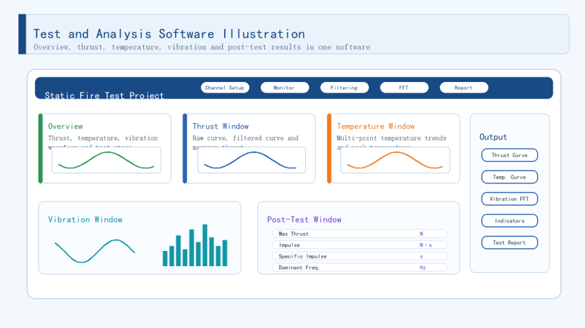
Figure 3 Test and analysis software illustration
III. Core Advantages
1. Synchronized data chain: The solution records thrust, temperature, and vibration signals under one time reference, reducing timestamp deviation caused by separate instruments and minimizing manual alignment after the test. This gives the entire static fire process better continuity and traceability.
2. Dynamic response and full-process recording: Thrust and vibration data can capture ignition shock, thrust build-up, and combustion-stage dynamic behavior. Temperature data can continuously record temperature rise on the engine case, near the nozzle, and at other key locations, as well as post-burn thermal response. This preserves the main physical process of a test.
3. Automatic key indicator calculation: With calculation templates in the test software, thrust, temperature, and vibration data can be filtered, integrated, and analyzed in the frequency domain. Results such as maximum thrust, burn time, total impulse, specific impulse, peak temperature, and dominant vibration frequency can be generated, turning curve records into engineering indicators that are easier to judge and compare.
4. Integrated acquisition and analysis workflow: One acquisition platform can support data acquisition, real-time display, filtering, data storage, and report output. This reduces data export, format conversion, and cross-software processing between multiple instruments, improving test review and report generation efficiency.
5. Expandability for test series: The same platform can adjust channel count, signal conditioning, sampling strategy, and report templates for different test stages. It supports small engine static fire tests, thrust stand validation, and case thermal response evaluation, helping establish consistent data structures and comparison criteria.
IV. Core Hardware Product Introduction
4.1 Data Acquisition Mainframe
The Doewe data acquisition mainframe serves as the acquisition, synchronization, storage, and software operating platform for the static fire test system. Depending on measurement point count and test stand layout, the solution can use a portable all-in-one acquisition mainframe, PXI/PXIe modular acquisition platform, or distributed acquisition front end. The mainframe manages thrust, temperature, and vibration modules together and provides a unified clock, trigger resources, and data storage.
For component-level tests with concentrated measurement points and moderate channel counts, a centralized acquisition structure can be used. For larger test stands or long-distance wiring scenarios, acquisition front ends can be deployed close to the sensors and connected to the test computer through a synchronized network. This helps reduce uncertainty caused by long-distance analog signal transmission.
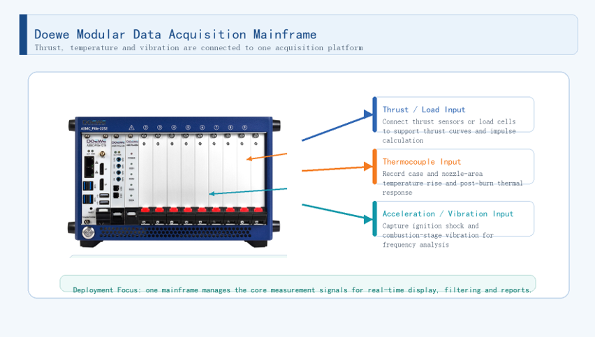
Figure 4 Doewe modular data acquisition mainframe
4.2 Thrust / Load Acquisition Module
Thrust is one of the most important performance data types in static fire testing. A thrust sensor or load cell is typically arranged in the load path of the test stand. The acquired thrust curve can be used to evaluate engine output capability, burn time, maximum thrust, total impulse, and specific impulse.
The Doewe solution can configure load, bridge, charge, or voltage signal conditioning modules according to the sensor type. Sensor calibration coefficients, engineering units, zero correction, and filtering can be completed in the software. For short-duration static fire tests, retaining both raw and filtered curves is important. Raw data helps review transient behavior, while filtered data supports indicator calculation.
4.3 Temperature and Vibration Acquisition Modules
The temperature module records temperature rise on the engine case, near the nozzle, and at other critical thermal response locations. Because heat transfer has a time delay, temperature may continue to rise after engine shutdown. Therefore, the test record should not stop immediately after combustion ends; a post-burn temperature record should be retained.
The vibration module acquires acceleration signals from the engine case, helping engineers observe ignition shock and dynamic response during combustion. Through filtering, time-domain replay, and FFT spectrum analysis, the main engine vibration frequencies can be extracted, providing a reference for structural matching, test review, and iterative design improvement.
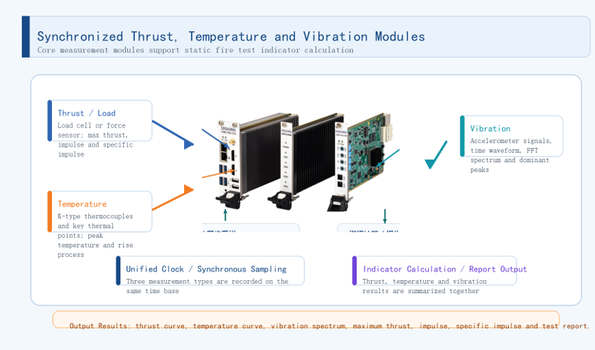
Figure 5 Synchronized thrust, temperature, and vibration acquisition modules
V. Typical Application Scenarios
Solid rocket motor static fire test: record thrust curves, burn time, case temperature rise, and engine vibration to evaluate maximum thrust, total impulse, specific impulse, peak temperature, and dominant vibration frequency.
Small engine thrust stand validation: build a unified measurement chain around load cells, thermocouples, and accelerometers to compare performance differences between configurations, propellant batches, or test rounds.
Engine thermal response evaluation: use multi-point temperature recording to observe temperature rise on the case and near the nozzle, and combine post-burn temperature behavior to evaluate heat transfer and structural condition.
Engine vibration characteristic evaluation: use case acceleration data and frequency-domain analysis to identify dominant frequency peaks, supporting the evaluation of ignition shock, combustion-stage dynamic response, and structural matching.
VI. Implementation Recommendations
At the beginning of the solution, the test object, test objective, and required output indicators should be clearly defined before establishing the measurement point list. Each measurement point should specify sensor type, installation location, range, sampling rate, engineering unit, calibration information, and naming rule.
Thrust sensor installation should consider load direction, test stand stiffness, and zero stability. Thermocouple placement should cover the case, nozzle area, and other key thermal response locations. Accelerometer placement and direction should be determined according to the vibration direction and frequency range of interest.
Recording should start before ignition and continue for a period after combustion ends. This preserves the pre-ignition baseline, combustion-stage dynamic response, and post-burn temperature change. During post-test analysis, thrust curves, temperature trends, vibration waveforms, and spectra should be reviewed together instead of drawing conclusions from a single curve.
VII. Summary
The core value of rocket engine static fire testing is not simply adding measurement channels. It lies in recording and analyzing thrust, temperature, and vibration under the same time reference. For engine tests with short test windows, fast dynamic changes, and high review cost, only synchronized data, a complete process record, and computable indicators can make test conclusions truly valuable for engineering decisions.
For static fire test requirements, Doewe Technologies can provide sensor and signal conditioning selection, DAQ hardware configuration, synchronized acquisition design, test software deployment, automated analysis templates, and report template delivery. Whether for small engine static fire tests, thrust stand validation, engine thermal response, or vibration characteristic evaluation, Doewe Technologies can provide a solution that better fits the customer's test workflow and data analysis goals.
Doewe Technologies is always committed to delivering innovative, distinctive, and reliable product solutions in the field of data acquisition. We draw inspiration for innovation from customers' real application needs. By continuously optimizing data acquisition, synchronized analysis, and engineering delivery workflows, we help partners build more efficient, more accurate, and more traceable test systems.