1. Solution Overview
In modern test systems, data acquisition is no longer judged simply by how fast, how many channels, or how much resolution it offers. In applications such as power electronics, electric drivetrains, structural vibration, rotating machinery, power semiconductors, energy storage systems, and distributed monitoring, what really determines whether results are trustworthy is often not single-point accuracy, but whether multiple channels, multiple boards, and multiple chassis can share the same time base and remain stably synchronized. Only when the time axis is unified can the relationships among voltage and current, force and displacement, speed and torque, analog and digital signals, bus messages and event triggers be analyzed, reproduced, and traced. The core goal of multi-device synchronization is, in essence, to give data from different sources strict time correlation.
Many engineering sites still view synchronization as simply having several devices start acquisition at the same time, but that addresses only the most superficial level of start-up consistency. True high-precision synchronization must satisfy at least four conditions at once: first, all acquisition nodes share a common reference clock; second, sampling edges can be aligned across channels and devices; third, trigger signals have deterministic transmission delay and low skew; fourth, over long recordings the system does not gradually drift out of sync because of local oscillator drift. PXI/PXIe has long been used for high-performance automated test and precision measurement precisely because the chassis backplane provides shared synchronization resources such as a common reference clock, trigger buses, star trigger, and a system timing slot. As a result, high-precision synchronous acquisition is not merely software-level clock alignment, but something built into the hardware architecture from the start.
For Doewe Technology, high-precision synchronous DAQ is not just a matter of inserting a few boards into a chassis; it is a complete systems-engineering effort built around clocks, triggers, sampling, calibration, compensation, recording, and analysis. For customer projects, the design must address channel synchronization within a board, multi-board synchronization within a chassis, and a unified time base across multiple chassis and even distance-separated deployments. Only by connecting all three layers of synchronization can a test platform scale smoothly from a small laboratory setup to complex system-level validation. That is the most fundamental difference between a high-end DAQ system and an ordinary recorder.
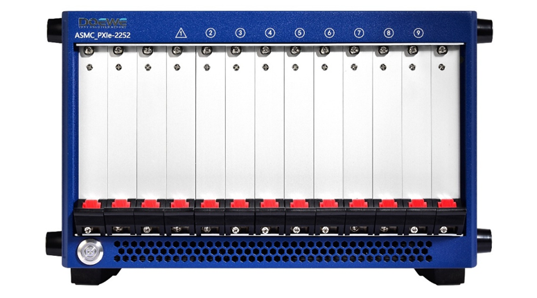
Figure 1 PXI/PXIe DAQ system diagram
2. The Essence of Synchronization
Why is synchronization so important? Because timing errors translate directly into amplitude error, phase error, and incorrect judgments about causality. For AC and periodic signals, a time offset can be converted directly into phase error:
Phase error = 360° × signal frequency × time offset.
A very intuitive example: if a 100 kHz signal has 100 ns of inter-channel skew, the phase error is 3.6°. If such an error appears in three-phase power analysis, motor-control algorithm verification, or inverter switching-behavior analysis, power, phase, efficiency, and even control judgments can all be affected. For nonperiodic events such as shocks, transients, and fault triggers, the impact is even more obvious: you may misjudge which event occurred first and thus reverse the true cause of the fault.
Therefore, a high-precision synchronization system is concerned not merely with the instant acquisition starts, but with consistency across the entire path from reference clock to sample generation. Common engineering error sources include scan delay between channels inside a board, clock-source drift between different boards, trigger-line skew, fixed group delay introduced by different ADC architectures, phase differences in front-end isolation and conditioning circuits, unequal external cable lengths, unstable distribution of the reference clock across chassis, and software-layer timestamps that are not generated by a unified hardware source. The value of a high-precision synchronization solution lies in progressively reducing and controlling these errors, and compensating for them in drivers and software when necessary.
3. Synchronization Mechanisms in PXI/PXIe
3.1 How Different Channels on the Same Board Are Synchronized
Within a single acquisition board, synchronization capability among channels first depends on the sampling architecture. The two most common approaches are multiplexed scanning and simultaneous sampling. In a multiplexed design, one ADC converts multiple input channels in sequence. Although the channels can belong to the same task, they are not truly digitized at the same instant; the device relies on the sample clock and convert clock to execute a sample-first, then convert one by one process, so a natural time order exists among channels. By contrast, a simultaneous-sampling architecture assigns each channel its own ADC, or at least its own sample-and-hold path, so all channels capture the input signal at the same sampling instant. This is better suited to phase analysis, transient reconstruction, and scenarios with high requirements for multi-channel dynamic consistency.
This means the first principle of board-level synchronization is not the more channels the better, but whether true simultaneous sampling is available. For applications such as three-phase power, vibration modal analysis, synchronous strain measurement, and shock testing, a scanning architecture may introduce non-negligible time differences between channels even if the nominal sampling rate is high, whereas a simultaneous-sampling architecture can compress this error to a very small range. In mature industrial simultaneous-sampling ADC designs, inter-channel skew of about 200 ps is already achievable, which is fundamentally different from multiplexed scanning.
But synchronization within a board is not determined by the number of ADCs alone. To turn sampled simultaneously into measured consistently, several key factors must also be considered: first, inter-channel aperture skew, meaning the offset between the sampling instants of different channels; second, matching of the front-end analog path, including gain, bandwidth, phase characteristics, and isolation structure; third, the quality of the board's internal reference clock, especially jitter; and fourth, factory calibration and run-time compensation mechanisms. For high-precision modules based on the delta-sigma architecture, the fixed group delay introduced by digital filtering also deserves special attention. In a homogeneous system, this delay is often identical across channels and cancels out in inter-channel phase comparison; but once different module types, sampling rates, or filter paths are mixed, group-delay compensation becomes mandatory, otherwise phase relationships and event correspondence will show systematic bias.
In other words, high-precision synchronization of different channels on the same board relies on three things: a simultaneous-sampling architecture, a common clock, and channel matching plus compensation. When selecting boards for customers, Doewe Technology first decides between simultaneous and scanning acquisition based on the frequency range of the signal under test, the required phase consistency, the presence of transient processes, and whether cross-domain correlation analysis is needed. For projects involving power, vibration, strain, or high-speed transient analysis, the first priority is consistent sampling instants, not simply the channel density on the datasheet.
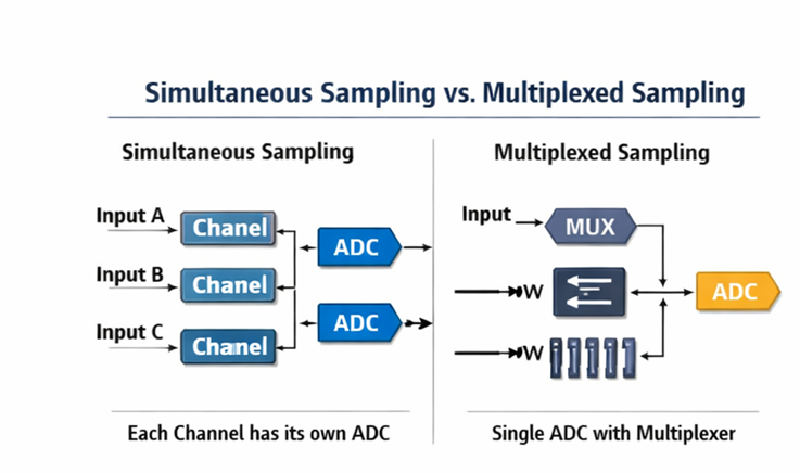
Figure 2 Comparison of multi-channel simultaneous sampling and scanning on the same board
3.2 How Different Boards in the Same Chassis Are Synchronized
When a test system expands from a single board to multiple PXI/PXIe boards in the same chassis, synchronization enters the second layer: how to make unified use of backplane clocks and trigger resources. The PXI platform provides the low-skew PXI_CLK10 reference clock, with the specification requiring skew of less than 1 ns between slots. The PXI star trigger bus, PXI_STAR, uses dedicated connections from the system timing slot to each peripheral slot to achieve low-skew triggering; its propagation-delay matching is also controlled within 1 ns, and the propagation delay from the star trigger slot to each slot must not exceed 5 ns. In other words, the standard PXI architecture already provides a shared time backbone for multi-board synchronization.
In the PXIe era, this capability was further strengthened. While retaining the PXI_CLK10 and PXI_STAR concepts, PXI Express also introduced the high-speed differential reference clock PXIe_CLK100, the differential synchronization signal PXIe_SYNC100, and the differential star triggers PXIe_DSTARA/B/C. PXIe_CLK100 distributes a low-skew 100 MHz reference clock to every peripheral slot; PXIe_SYNC100 indicates the phase relationship between the 10 MHz and 100 MHz references so that different modules remain aligned during division and phase alignment; and PXIe_DSTARA/B/C provide high-quality point-to-point clock/trigger connections, suitable respectively for high-speed clock distribution, high-speed trigger distribution, and returning clocks or triggers from peripherals. The PXIe system timing slot is the hub for these high-performance synchronization resources.
In practical engineering, synchronization of multiple boards in the same chassis usually follows this path: first, choose a reference clock source, which may be the chassis oscillator or an external 10 MHz reference with higher stability; then use a system timing module or master device to route that reference onto the backplane; each board locks its local PLL or internal sampling time base to the shared reference; then distribute key synchronization signals such as the start trigger, reference trigger, and sample clock enable to all participating modules through PXI_TRIG, PXI_STAR, or differential star-trigger lines. The result is that all boards not only receive the same start command, but begin operating on predictable sampling edges under the same reference-clock constraints.
If the project requires even tighter phase consistency, backplane distribution alone is often not enough. Sample clock alignment, trigger skew correction, and device-to-device calibration at the driver or synchronization-library level are often required as well. Mature PXI software synchronization mechanisms can automatically align sampling clocks and trigger responses for multiple devices in a single chassis and even across multiple chassis. Public information shows that, under standard synchronization mechanisms, typical multi-device skew can reach the 200-500 ps range, and with further manual calibration it can be compressed to tens of picoseconds. For systems highly sensitive to relative timing, such as high-speed waveforms, RF front-end verification, and phased-array measurement, this combination of hardware backbone, driver compensation, and calibration correction is crucial.
It must be emphasized that true synchronization of different boards in the same chassis cannot be judged merely by whether they are physically installed in one chassis. If board types are mixed, ADC architectures differ, filter paths differ, or acquisition tasks are split into multiple unrelated workflows, the final data may still fail to share a common time reference even though the hardware is co-located. For this reason, when integrating multi-board systems in one chassis, Doewe Technology focuses on board-family compatibility, multi-device synchronization support in the driver, group-delay compensation capability, use of the chassis timing slot, and clock and trigger routing, rather than leaving synchronization to be patched together later in software.
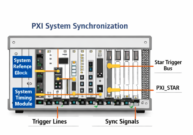
Figure 3 Clock and trigger synchronization of multiple boards in the same chassis
3.3 How Different Chassis Are Synchronized
As the system continues to grow, a single chassis may no longer hold all channels, or the measurement points themselves may be distributed across different cabinets, test stands, or lab areas. This introduces the third layer of synchronization: cross-chassis synchronization. Unlike synchronization within a chassis, this scenario must address not only low skew, but also long distance, long duration, and an absolute time reference. Put simply, cross-chassis synchronization must answer two questions: can multiple chassis operate on the same sampling edge, and can they remain aligned over sufficiently long recording times without noticeable drift?
The most direct and common method is to connect multiple chassis through a shared reference clock plus a shared trigger. For example, the master chassis or an external high-stability source outputs a 10 MHz reference, which is distributed to the system timing module of each chassis, and a common start trigger or PPS pulse is then used to start acquisition. The advantage is good relative phase consistency, making it suitable for laboratories, high-speed waveforms, phase measurement, and joint analysis of multiple power channels. At high sampling rates, special attention must also be paid to the jitter of the reference clock itself and to matching cable lengths from the source to each chassis, because both directly affect final phase consistency.
For systems distributed over larger distances and requiring a unified absolute time, common approaches include IEEE 1588/PTP, IEEE 802.1AS, GPS, IRIG-B, and PPS. Public information shows that PXI timing and synchronization modules already support bringing these protocols and time sources into PXI/PXIe systems and converting absolute time into hardware events that can be used for sampling and triggering. In typical multi-chassis solutions based on IEEE 1588, public documentation gives a typical synchronization accuracy on the order of 100 ns. For long-distance distributed monitoring, the value of such a solution is not just starting together, but ensuring that data acquired by different chassis carries a unified absolute time stamp for event correlation, historical traceability, and cross-system analysis.
Of course, there is no single cross-chassis synchronization answer that fits every scenario. If the goal is the highest phase consistency, shared hardware clocks and a common trigger should be considered first. If the goal is wide-area deployment with unified time stamps, PTP, GPS, or IRIG-B should take priority. If both phase consistency and cross-region time traceability are required, a hybrid architecture of absolute-time protocol plus local hardware clock disciplining is often used. That is why a truly mature cross-chassis synchronization solution is never just the sale of a sync card; it must be designed in combination with test distance, sampling rate, signal frequency, allowable phase error, recording duration, network topology, and deployment environment.
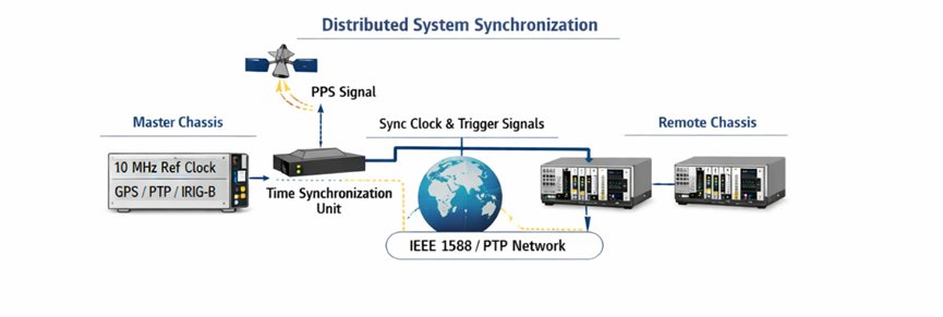
Figure 4 Architecture of a unified time base for multi-chassis synchronization
4. Advantages of the Doewe Technology Solution
Building on the three layers of synchronization above, Doewe Technology treats a high-precision synchronous DAQ solution as a unified architecture that scales smoothly from a single board to a distributed multi-chassis system. For customers, the greatest value is not how attractive the standalone specifications of a particular board look, but that reference-clock planning, trigger paths, board combinations, synchronization calibration, filter-delay compensation, long-duration recording, and post-processing analysis can all be considered together from the start of the project. A platform built this way may start as one chassis with dozens of channels and later expand to multiple chassis with hundreds or more channels without overturning the original data logic or time-base logic.
First, the Doewe Technology solution emphasizes a unified time-base design from channel level to system level. At the board level, it focuses first on whether the architecture is simultaneous sampling and whether good channel consistency is available. At the chassis level, it fully leverages the reference clock, star trigger, and system timing slot resources provided by the PXI/PXIe backplane. At the multi-chassis level, it selects synchronization paths such as a shared 10 MHz reference, PPS, PTP, GPS, or IRIG-B according to project goals. The benefit is that the solution defines its synchronization boundary and accuracy boundary from the beginning, so the customer receives not a pile of discrete hardware, but a verifiable and scalable synchronized measurement platform.
Second, the Doewe Technology solution emphasizes the fusion of multiple signal types on a common timeline. In real projects, customers rarely care only about analog voltage. More often they care about the relationships among voltage, current, temperature, strain, vibration, speed, torque, digital I/O, encoders, CAN messages, Ethernet status variables, and even external device events. The significance of high-precision synchronization is not only to synchronize similar analog channels, but to bring all of these heterogeneous data sources onto one unified time system. Only then do efficiency analysis, fault localization, electromechanical coupling studies, control-logic verification, and system-level playback gain real engineering value. The related capabilities - automatic synchronization across multiple devices, trigger-skew correction, and group-delay compensation - are exactly what enable a mature PXI/PXIe DAQ platform to support complex test tasks.
Third, the Doewe Technology solution emphasizes accuracy assurance during engineering delivery. High-precision synchronization is not a term printed in a manual; it must actually run correctly on site. Many projects fail not because the boards themselves lack accuracy, but because clock distribution is poorly designed, cable lengths are inconsistent, grounding and isolation are mishandled, filter delays of different modules are not compensated, or different acquisition tasks are artificially split apart, so that something theoretically synchronized cannot be aligned in the field. The value of Doewe Technology lies in pushing these often-overlooked details forward into solution design, integration, and delivery, so synchronization accuracy exists not only under laboratory conditions but also in the customer's real operating environment.
Fourth, the Doewe Technology solution emphasizes localized application integration and delivery efficiency. For many users, the real challenge is not purchasing PXI/PXIe hardware, but turning hardware, sensors, front-end conditioning, clock synchronization, data recording, analysis software, report templates, and automation workflows into a system that can operate reliably over the long term. Doewe Technology can provide test-point planning, hardware configuration, synchronization-scheme design, software deployment, and application-layer delivery around the customer's test object, helping the customer move faster from equipment procurement to a usable platform. This is also Doewe Technology's most practical and differentiating advantage in the field of synchronized DAQ.
5. Typical Application Scenarios
In power-electronics testing, high-precision synchronization is first reflected in the joint acquisition of multi-phase voltage and current signals together with control-state variables. Taking inverters, converters, energy-storage PCS, OBC, and DC/DC as examples, if input-side DC quantities, output-side AC quantities, gate-control signals, temperature rise, CAN states, and protection events do not share the same time base, many anomalies can only look roughly similar and a real causal chain cannot be established. A synchronized system, by contrast, can fully connect input energy, control actions, switching behavior, and output response for efficiency evaluation, switching-transient analysis, fault tracing, and protection-strategy verification.
In automotive e-drive and rotating-machinery testing, the value of synchronization lies more in correlating electrical and mechanical quantities. Motor three-phase current, DC bus voltage, speed, torque, vibration, temperature, and controller status must all be aligned simultaneously in order to accurately calculate efficiency, loss, electromechanical coupling characteristics, and dynamic behavior during start-stop events and load steps. If channel synchronization is inadequate, phase calculations may diverge at best; at worst, control issues may be misdiagnosed as mechanical problems, or mechanical resonance may be mistaken for current abnormalities.
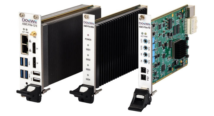
Figure 5 Doewe Technology high-precision synchronous DAQ card
In large laboratories and distributed monitoring scenarios, cross-chassis synchronization is reflected again in system scalability. One chassis can handle local high-density acquisition, while multiple chassis can be deployed across different cabinets, benches, or even different areas, and then tied into one unified recording system through a shared clock or an absolute-time protocol. This architecture is especially suitable for large-scale benches, structural tests, environmental coupling tests, long-distance power-equipment monitoring, and systems requiring joint playback of multi-source data.
6. Implementation Recommendations
From an implementation standpoint, if a project involves only multiple dynamic channels within the same board and the focus is phase and transient consistency, a simultaneous-sampling module should be chosen first. If the project has already grown to multiple boards within one chassis, the system timing slot, a common reference clock, and a defined trigger-distribution path should be introduced as early as possible; relying on software start timing to approximate synchronization is not recommended. If cross-chassis expansion is needed, one should first distinguish whether the requirement is high phase consistency or unified absolute time, and then decide between a shared-clock scheme and a PTP/GPS/IRIG-B scheme. For systems with mixed ADC architectures or mixed sampling rates, group-delay compensation must be part of the design rather than assuming that everything placed in one system will automatically be synchronized.
In addition, the higher the synchronization accuracy required, the less these details can be ignored. Cable-length matching, connector quality, chassis grounding, shielding and isolation design, reference-clock stability, trigger-edge quality, driver-level synchronization capability, and calibration and verification procedures may all look like supporting details, but they ultimately appear as phase error, event-alignment error, and long-term drift. A truly mature solution does not treat synchronization as a feature of one module, but as the underlying methodology of the entire test system.
7. Conclusion
The core of high-precision synchronous data acquisition is not whether devices start working together, but whether all data can be acquired, recorded, and analyzed reliably under a common time reference. In PXI/PXIe systems, this capability can be understood on three levels: within a single board, simultaneous sampling and channel matching ensure consistent sampling instants; within a single chassis, the backplane reference clock, star trigger, and system timing slot enable low-skew synchronization across multiple boards; across different chassis, shared reference clocks, common triggers, and external time systems such as PTP, GPS, IRIG-B, and PPS extend synchronization to larger and more distributed systems.
Along this technical path, Doewe Technology can provide customers with a complete solution spanning test-point planning, hardware configuration, clock and trigger design, software deployment, synchronization verification, data analysis, and application delivery. For projects requiring high phase consistency, large channel scalability, and complex system-level correlation analysis, this ability to synchronize from board to system and from one chassis to many is the real value of the test platform. Doewe Technology will continue to turn this capability into a DAQ platform that is more stable, more flexible, and closer to real field needs, helping customers move beyond merely acquiring data to acquiring it accurately, aligning it correctly, explaining it clearly, and reproducing it reliably.
Doewe Technology remains committed to delivering innovative, distinctive, and reliable product solutions in the field of data acquisition. We understand that these qualities are the foundation on which companies compete in the market. For that reason, our innovation is driven by customers' real application needs, not by the pursuit of flashy but impractical features. By continuously optimizing and improving data-acquisition solutions, Doewe Technology helps partners move toward a more efficient and precise future. Choose Doewe Technology and open a new chapter in data acquisition together.