1. Solution Overview
With the rapid development of new energy vehicles, photovoltaic generation, energy storage systems, and various power-electronics equipment, power testing has evolved from simple voltage and current logging into comprehensive evaluation of power, efficiency, energy flow, harmonics, dynamic response, and system stability. Whether for product development, performance verification, type testing, or onsite troubleshooting, the core of testing still relies on a data acquisition system that can obtain key data stably, synchronously, and traceably. A DAQ system determines not only whether something can be measured, but whether it can be measured accurately, completely, and clearly.
In power testing, truly valuable data are never just the voltage or current at a single moment, but the correspondence among different test points and physical quantities on a common time base. Input-side voltage and current, output-side power and energy, equipment temperature, speed, torque, switching states, bus diagnostic codes, and environmental parameters must be acquired, stored, and analyzed in a unified way to build a complete evaluation chain from input electrical energy to system state to output performance. Especially in inverter switching, load transients, start-stop transitions, and fault transients, preserving raw waveforms and supporting post-processing recalculation are often the key to rapid troubleshooting and behavior reconstruction.
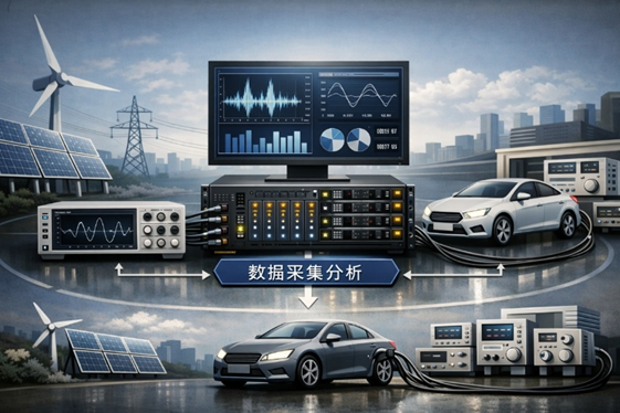
Figure 1. Power Testing
In automotive power testing, DAQ systems are widely used for traction batteries, drive motors, motor controllers, onboard chargers, DC/DC converters, and vehicle high-voltage systems. The system can synchronously acquire HV bus voltage/current, phase voltage/current, control states, temperature rise, speed, torque, and other signals for efficiency analysis, energy-regeneration analysis, steady-state and transient comparison, and dynamic evaluation during startup, acceleration, regenerative braking, load steps, and similar processes. In both bench testing and on-road vehicle testing, the DAQ system provides the common time base, unified recording, and unified analysis foundation.
In photovoltaic power testing, DAQ systems are typically used for synchronous measurement of the PV array input side and the inverter output side. By simultaneously acquiring DC-side voltage/current and AC-side single-phase or three-phase voltage/current, the system can quickly establish the relationship among input power, output power, conversion efficiency, grid-connection quality, and dynamic response. When combined with ambient temperature, irradiance, or equipment communication data, it can also be used to analyze MPPT performance, power-control strategy, grid-connection switching, and sources of abnormal fluctuations. Such multi-source synchronized testing is especially important for PV inverters, energy-storage inverters, and power-conversion units.
Therefore, a DAQ system for power testing should not be viewed merely as a “recording device,” but as a complete test and analysis platform. It must cover high-voltage, high-speed, and high-accuracy measurement, while also providing power calculation, energy statistics, multi-source synchronization, triggered recording, data playback, automatic reporting, and interface linkage, so that it can truly support applications such as automotive power testing and photovoltaic power testing. For enterprises, a mature DAQ platform not only improves test efficiency, but also significantly enhances the consistency and credibility of test results.
Doewe Technology can provide complete solutions for different power-test objects, covering measurement-point planning, sensor integration, acquisition hardware configuration, test software deployment, and report template output. For both new test platforms and upgrades of existing systems, the configuration can be tailored to the DUT, measurement range, operating profile, and target specifications. A schematic of the test system architecture is shown below:
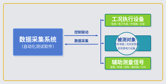
Figure 2. Power Test System Architecture
2. Test System Description
2.1 Test System Principles
Through coordinated hardware and software, the platform can synchronously measure and analyze voltage, current, power, energy, and related status variables of the DUT under different operating conditions. During testing, voltage signals can be connected directly to high-voltage or low-voltage acquisition channels, or routed through HV differential probes or isolated transmitters for range scaling and isolation according to voltage level, isolation safety, and onsite interference. Current signals can be converted and connected through shunts, Hall current sensors, Rogowski coils, or zero-flux current sensors. In addition to electrical parameters, the system can also synchronously acquire temperature, speed, torque, encoders, digital I/O states, CAN, Modbus TCP, and other information, ensuring that all data are acquired, displayed, and analyzed on a unified time base.
In automotive power testing, measurements are typically organized around the “battery–inverter–motor–load” chain. On the input side, HV bus voltage and current can be acquired; on the output side, motor phase voltage and current can be acquired; and mechanical variables such as speed and torque can be synchronously included as required, enabling efficiency, loss, and dynamic-response analysis. In PV and energy-storage testing, the system can simultaneously acquire the DC-side input of the PV array or storage system and the AC-side output of the inverter, enabling joint evaluation of conversion efficiency, output stability, grid-connection quality, and control strategy.
The system can also perform repeatable verification of processes such as start/stop, loading, step changes, and fault injection through trigger conditions, event markers, and automated process configuration. The test software can output RMS, average, active power, reactive power, apparent power, power factor, energy, and other parameters in real time, while also preserving raw waveforms for offline recalculation and troubleshooting. Raw waveform recording is especially important for transient processes such as inverter switching behavior, short-duration shocks, grid disturbances, and load steps. The principle of power testing is as follows:
2.2 Test and Analysis Software
The test and analysis software is installed on the control platform and integrates device management, channel configuration, real-time display, process control, and data analysis. In a single interface, the software can configure voltage, current, temperature, speed, torque, encoder, and bus channels, and supports range setting, sensor scaling, wiring definition, power-group configuration, trigger setting, and data-record management. In power testing, its core role is to automatically convert raw measured signals into the engineering metrics that users actually care about, and to present data from different sources in a unified way.
For power analysis, the software supports single-phase, three-phase, and multiphase power-system configurations, supports power calculation under different wiring topologies, and provides cycle-by-cycle gap-free computation, automatic fundamental-frequency identification, raw-data visualization and storage, and consistent online/offline analysis workflows. Common parameters such as RMS, average, active power, reactive power, apparent power, energy, and power factor can all be displayed in real time. For more complex tasks, harmonic analysis, power quality, mechanical power, and efficiency analysis can also be added.
In automotive e-drive and motor testing, the software can incorporate mechanical variables such as speed and torque into a unified calculation chain, forming a closed-loop evaluation of “electrical input–mechanical output–efficiency and loss.” In PV inverter testing, it can link communication data with external measurements to identify key issues in control logic, power fluctuation, and grid-connection behavior. The software architecture supports automated test-sequence configuration, allowing data acquisition, storage, calculation, and standardized report generation to run automatically according to predefined conditions, significantly reducing manual operations and improving test efficiency and result consistency. A software schematic is shown below:
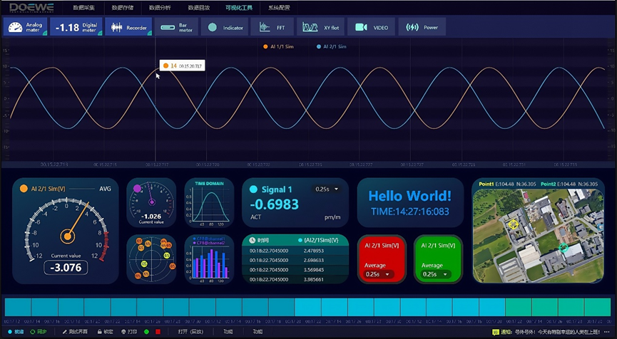
Figure 3. Test and Analysis Software
3. Core Advantages of the Solution
- Unified testing for multiple scenarios: One platform can cover automotive and photovoltaic power testing, reducing duplicate investment and helping enterprises build a unified data and reporting system.
- Integrated electrical and status-data acquisition: In addition to voltage and current, the system can synchronously acquire temperature, vibration, speed, torque, encoders, and bus data, enabling multidimensional correlation analysis.
- High voltage, high speed, and high accuracy in one system: It supports both steady-state efficiency and energy-consumption evaluation, and transient tasks such as inverter switching, rapid dynamics, and load steps.
- Multi-source data synchronization: Analog signals, digital I/O, counters, buses, and external clocks can all be aligned on one reliable time base for complex system analysis.
- Retention of both raw waveforms and statistical results: Users can view engineering metrics directly and trace anomalies back to waveform level, improving troubleshooting efficiency.
- High degree of automation: Template-based test-sequence configuration, automatic execution, automatic logging, and automatic report output reduce manual error and improve test consistency.
- Flexible platform expansion: Power channels, temperature channels, auxiliary analog channels, or bus channels can be added according to project scale, adapting to different DUTs and future upgrades.
- Easy system integration: The platform can interface with existing power supplies, loads, benches, environmental chambers, controllers, and host-computer systems, shortening overall deployment time.
- Custom delivery support: Doewe Technology can provide customized configuration from measurement-point planning to complete test-solution delivery according to the customer’s DUT, operating conditions, and target specifications.
4. Core Hardware Products
4.1 Data Acquisition Modules
4.1.1 Overview of Data Acquisition Modules
The control, storage, and acquisition modules are integrated on the same platform based on a modular architecture. According to project needs, high-voltage power acquisition modules, general-purpose analog acquisition modules, temperature modules, counter/encoder modules, and bus-interface modules can be flexibly combined to achieve integrated acquisition of electrical parameters, mechanical quantities, environmental variables, and status data. The platform is suitable for laboratory and bench environments and can also be extended to vehicle-mounted or field-deployment scenarios as required. For power testing, the advantage of this modular design is that a dedicated system can be quickly built around a specific DUT, while channels and functions can continue to expand as needs grow, without rebuilding the entire system from scratch. A product schematic of the control and storage module is shown below:
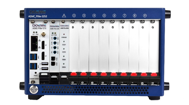
Figure 4. Data Acquisition Module
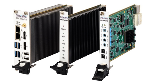
Figure 5. Power Acquisition Module
4.1.2 Key Parameters of the Data Acquisition Modules:
High-Voltage Power Acquisition Module
- 3750 Vrms(1 min)Each module supports 4-phase power analysis; sampling rates from 100 S/s to 2 MS/s; 24-bit resolution
- Fixed high-voltage input supports ranges up to 1000 Vrms / 2000 VDC; analog bandwidth up to 5 MHz
- Designed for high-voltage power testing; supports safety ratings of 600 V CAT IV / 1000 V CAT III, with channel-to-ground isolation withstand voltage up to 3750 Vrms (1 min)
Multi-Source Synchronization and Data Processing Platform
- The modular chassis supports combinations of system, timing, and hybrid slots; system bandwidth up to 24 GB/s and per-slot bandwidth up to 8 GB/s
- The controller supports high-performance processors, 16 GB or more memory, and high-speed bus switching, making it suitable for long-duration continuous recording and online computation
- Provides 10 MHz clock I/O and multi-chassis synchronization for unified time-base acquisition across multiple devices and measurement points
High-Speed Storage Module
- Based on NVMe solid-state storage architecture, with expandable capacity up to 16 TB
- Sustained read/write bandwidth can exceed 6 GB/s, suitable for long-duration raw waveform recording and high-speed data playback
- Supports direct-to-disk writing with high-speed caching to meet storage-throughput requirements in multi-channel synchronized recording scenarios
Sensor Power Supply and Signal Conditioning Module
- Supports programmable 5–24 V DC sensor power supply; output current per channel not higher than 300 mA; supports 24 V / 4 mA IEPE constant-current source
- Enables unified sensor power supply, power-on control, and undervoltage monitoring, facilitating centralized management of bench-test systems
General-Purpose Analog Acquisition Module
- Supports multiple input types including voltage, bridge, resistance, RTD, IEPE, current, and counter inputs
- Per-channel sampling rate up to 5 MS/s and analog bandwidth up to 2 MHz, suitable for temperature, vibration, speed, torque, and auxiliary electrical signals
- Supports unified access and synchronized acquisition of multiple sensor types, facilitating joint analysis of electrical parameters and status data
Digital I/O / Bus Interface Module
- Supports expansion of digital inputs, encoders or counters, CAN, UART, Ethernet, and other interfaces
- Can access control commands, device status, diagnostic codes, and communication data, aligning control variables and measured variables on the same timeline
- Shares the system time base to synchronously record analog, digital, and bus data, facilitating complex system testing and post-processing analysis
5. Summary
For automotive power testing, photovoltaic power testing, and other scenarios, Doewe Technology can provide complete solutions covering measurement-point planning, sensor and probe selection, data-acquisition hardware configuration, test-software deployment, automated workflow development, and report-template delivery. Whether building a new test platform or upgrading an existing system, Doewe Technology can provide solutions better matched to real application needs based on the customer’s DUT, operating characteristics, and test objectives. If you are planning a related test system, you are welcome to contact Doewe Technology for further discussion.
Doewe Technology is always committed to delivering innovative, distinctive, and reliable product solutions in the field of data acquisition. We understand that these qualities are the foundation for enterprises to gain a firm foothold in market competition. That is why our innovation is driven by customers’ real application needs, rather than by the mere display of flashy but impractical product features. By continuously optimizing and improving data acquisition solutions, Doewe Technology helps its partners move toward a more efficient and precise future. We welcome you to choose Doewe Technology and open a new chapter in data acquisition together.