1. Introduction
Wireless emergency broadcasting offers advantages such as rapid dissemination, broad coverage, convenient reception, and independence from power constraints. During emergencies like natural disasters, accidents, public health crises, and social safety incidents, especially when power and communication networks are disrupted, government authorities can still use emergency broadcast systems for mobilization and task deployment. This enables them to convey disaster information or potential hazards to the public, informing them promptly about the situation and necessary actions for evacuation and safety. Furthermore, the development of rural emergency broadcasting systems is a crucial means to enhance public cultural services in rural areas and support the construction of a new socialist countryside. As a transmission channel for public cultural information dissemination, rural emergency broadcasting systems can routinely communicate decisions and policies from Party committees and governments at all levels, enriching the cultural lives of the masses. This plays a pivotal role in consolidating and strengthening grassroots cultural propaganda efforts, unifying thinking, and rallying public support.
FM-RDS wireless emergency broadcasting utilizes wireless FM frequencies within the 76~87MHz or 88~108MHz bands to transmit audio signals. An RDS control signal is embedded in the 57KHz subcarrier channel, forming this emergency broadcast transmission mode. The core characteristic of the FM-RDS wireless emergency broadcast system is its "wireless" transmission; the propagation of audio and control signals relies solely on electromagnetic wave transmission through the air, requiring no network support. Emergency broadcast terminals can be installed wherever local FM radio coverage exists, enabling wireless emergency broadcast coverage. The system also boasts strong scalability, allowing easy addition of terminals wherever the receiver turn-on level can be met.
For FM-RDS system testing, our company's RWC2100F equipment fully satisfies the testing requirements for both RDS transmitters and RDS receivers, providing extensive instrumentation convenience for manufacturers, universities, and research institutes.
2. Test Overview
For FM-RDS, our company utilizes the RWC2100F to establish the following two application scenarios:
● FM-RDS Receiver Test
● FM-RDS Transmitter Test
2.1 FM-RDS Receiver Test
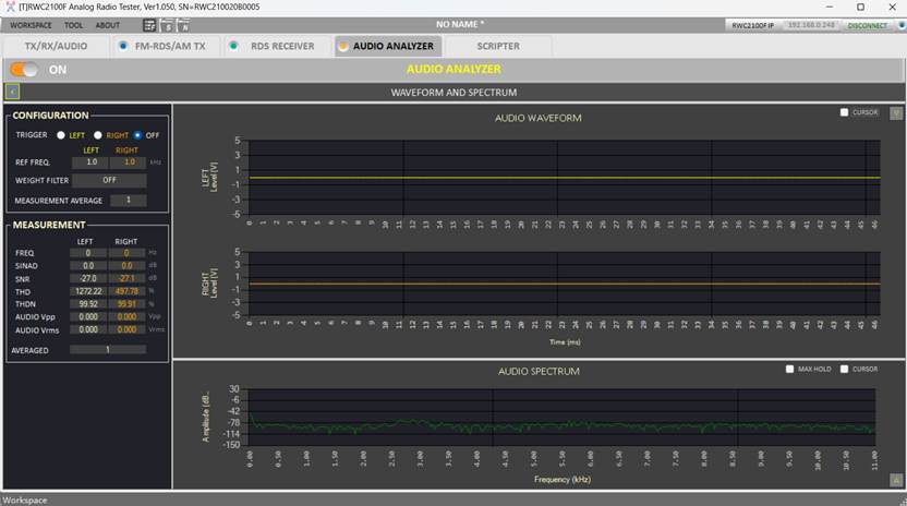
The test subject is the FM-RDS receiver. Using our RWC2100F, standard FM-RDS signals can be generated with editable RDS information functionality, enabling comprehensive and controllable receiver functional testing. Additionally, the RWC2100F possesses audio analysis capabilities. By sending a signal, having the receiver receive it, and simultaneously analyzing the audio signal output by the receiver, a loopback test is formed, providing a full assessment of the receiver's RDS reception performance.
2.2 FM-RDS Transmitter Test
The test subject is the FM-RDS transmitter. Using our RWC2100F, real-time monitoring of FM-RDS content is possible. This includes TA (Traffic Announcement), TP (Traffic Programme), EON (Enhanced Other Networks), AF (Alternative Frequencies) information, as well as extended text and time content within the RDS data, enabling comprehensive transmitter content testing.
3. Test Plan
Beijing Doewe Technologies Co., Ltd. has developed a fully compliant test plan for FM-RDS, meeting the requirements for standardized testing across various scenarios.
4.1 FM-RDS Receiver Test
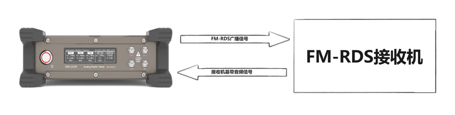
Figure 4: Complete Unit Test Connection Diagram
Description: The test system consists of the RWC2100F Emergency Broadcast Tester and the Device Under Test (DUT) receiver.
The RWC2100F outputs an FM-RDS broadcast RF signal. This signal is connected to the FM-RDS receiver via an open field (OTA) or cable connection. The receiver receives the signal, demodulates it, and outputs the baseband audio signal back to the RWC2100F for audio signal analysis.
The RWC2100F can simultaneously output three RDS signals to three RDS receivers for parallel reception testing.
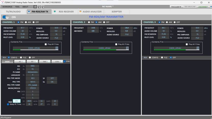
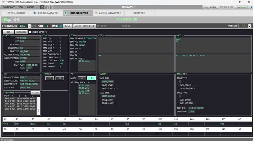
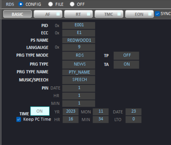
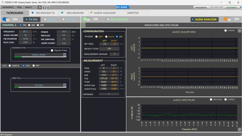
RWC2100F FM-RDS Signal Generator Settings Interface:
RWC2100F FM-RDS Audio Analysis Settings Interface:
RWC2100F FM-RDS Loopback Test Interface:
4.2 FM-RDS Transmitter Test
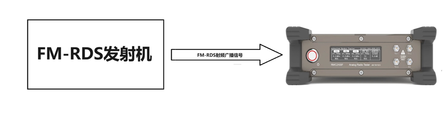
Figure 5: Player Test Connection Diagram
Description: The test system consists of the RWC2100F Emergency Broadcast Tester and the DUT transmitter.
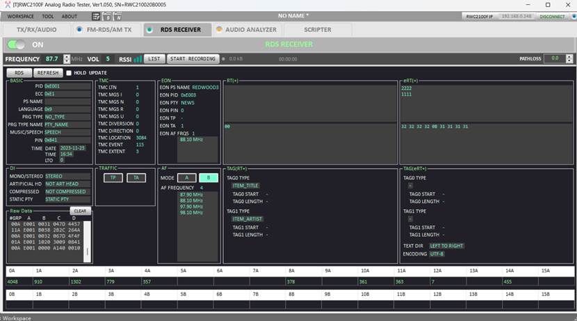
The RF signal output from the transmitter is connected to the RX RF signal input port of the RWC2100F. The RWC2100F then receives the signal, demodulates it, and displays the complete RDS signal content.
RWC2100F FM-RDS Signal Analysis Interface:
4. Core Test Equipment Introduction
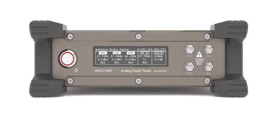
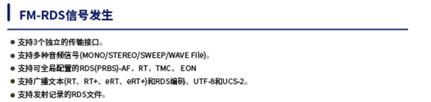
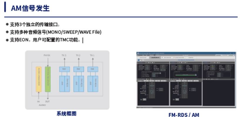
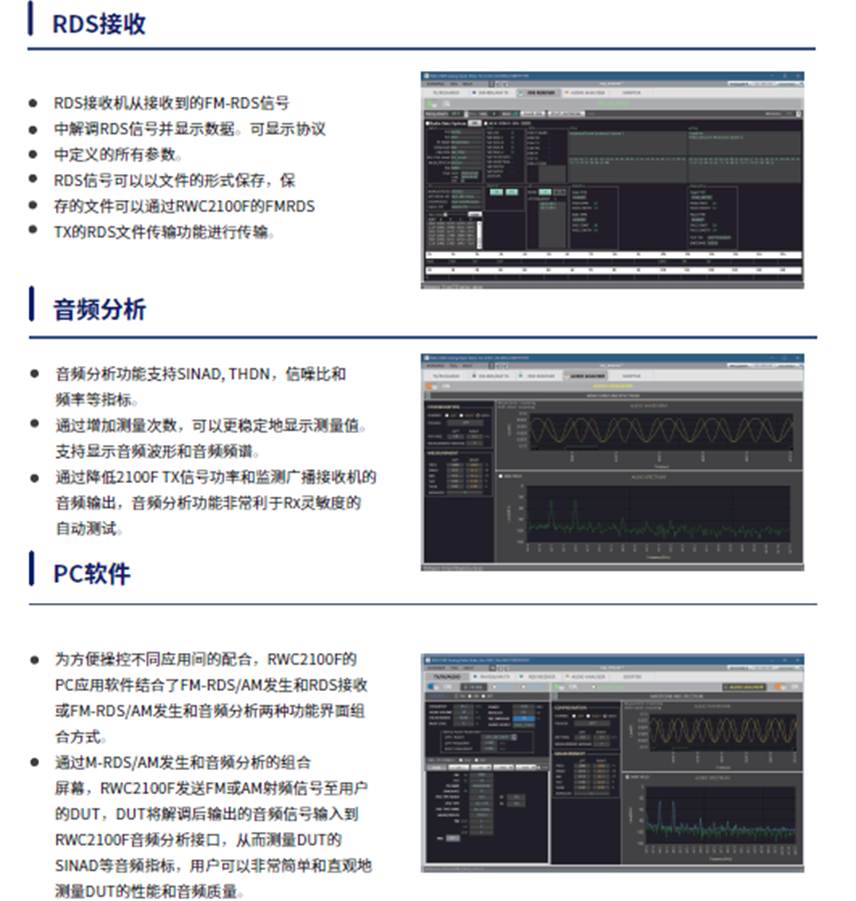
The RWC2100F is a multi-channel emergency broadcast tester providing FM-RDS, AM, RDS reception, and audio analysis capabilities. It supports 3 RF signal generator interfaces, each configurable as FM-RDS or AM. The FM-RDS generator offers numerous editable protocol parameters such as PI (Program Identification) Code, PS (Program Service) Name, (e)RT(+) (RadioText). It also provides functional tests like AF (Alternative Frequencies), EON (Enhanced Other Networks), and TMC (Traffic Message Channel). The RDS reception function captures RDS signals via the RF input and displays RDS parameters. Received RDS signals can be recorded to a file for later playback using the FM-RDS generator function.
The RWC2100F's audio analysis function not only measures audio signal quality (SINAD, THD+N, SNR) and frequency but also displays audio waveforms and audio spectra. All functions can be controlled via PC software, and all parameters can be saved and loaded.