1. Introduction
Closed-circuit television (CCTV) monitoring systems are an indispensable and crucial component of highway traffic infrastructure. They bear the responsibility of uploading real-time road traffic conditions to the road monitoring command center, enabling timely understanding of conditions in various areas to ensure prompt responses during incidents. The corresponding video monitoring links, serving as carriers for transmitting video signals, impact multiple aspects such as video quality, signal transmission speed, and transmission stability. Therefore, evaluating the transmission quality of these links and conducting regular inspections are particularly important.
For traditional analog video signals, such as CCVS (Analog Composite Video Signal for Standard Definition) and YPbPr (Analog Component Video Signal for High Definition), testing the corresponding analog video transmission systems is typically performed directly through analog video interfaces. With the digitization of signals, video transmission systems based on HDMI interfaces have also gradually been applied to the transmission of analog signals (requiring a prior digitization process). Simultaneously, to maintain good video quality, some systems also consider using optical transmitter and receiver systems to directly modulate and transmit analog signals (or even digitized HDMI signals) via light. Therefore, testing video signals based on HDMI interfaces is also necessary. Furthermore, with technological advancements, IP networks are gradually becoming mainstream. Accordingly, CCTV monitoring systems are continuously transitioning towards IP-based video transmission, and some cameras can directly output IP video data.
The digitization of video and transmission over IP networks are two complementary and co-developing technological trends. Concurrently, video resolutions are constantly increasing, with high-definition (HD) video signals now being the mainstream application in highway settings. Due to the large volume of video data (especially HD video) transmission, the transmission network must possess good performance. Moreover, processing at various levels increases the possibility of packet loss during transmission. Hence, a test solution specifically targeting HD video IP transmission networks is imperative.
2. Transmission System Introduction
2.1 Traditional Analog Video Transmission System
To maintain good transmission quality, traditional analog video transmission systems often employ optical transmitters and receivers. The analog signal (or even a digitized HDMI signal) is optically modulated by an optical transmitter for transmission, then demodulated by an optical receiver before being input to the next stage of the system. As shown in Figure 1:
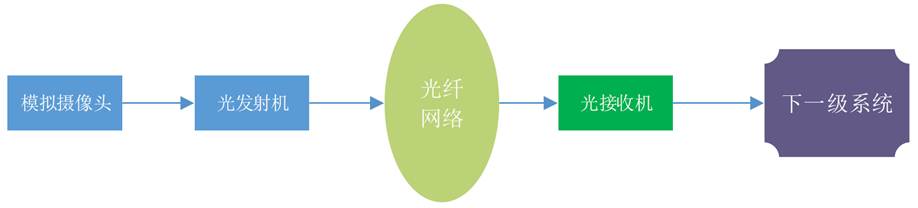
Figure 1: Optical Transmitter/Receiver Transmission System
This transmission system can support Standard Definition (SD) analog composite video signals (CCVS), High Definition (HD) analog component video signals (YPbPr), and digitized HDMI video signals.
2.2 IP Network-Based Video Transmission System
From the perspective of current mainstream industry applications, IP network-based video transmission systems are divided into two types: those with encoders/decoders and those without. Systems with encoders are used to be compatible with traditional cameras, while systems without encoders utilize IP network cameras that can directly output IP video signals.
Testing IP network-based video transmission presents a challenge, as it requires consideration of both the characteristics of the actual transmission system and the testing conditions that instrumentation can provide.
2.2.1 IP Transmission System with Encoder/Decoder
The core network of a video transmission system with encoders/decoders is an IP network. Encoders and decoders are used to IP-ify video signals, enabling their transmission over the IP network. A typical schematic is as follows:
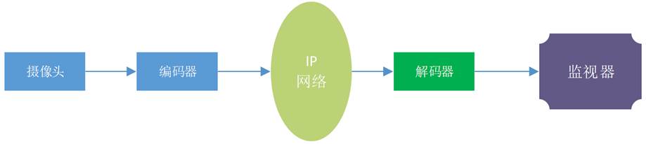
Figure 2: Traditional IP Transmission System with Encoder
If the camera is an SD camera, the encoder needs to support SD formats. The video encoder compresses and encodes the input uncompressed or lightly compressed video data, encapsulates it into a Transport Stream (TS), and outputs it to the IP transmission network via an ASI interface or as SDI over IP. Typical SD video encoders primarily accept inputs like SD analog composite video (CCVS) or SDI interfaces, with some commercial products also supporting HDMI interfaces. Similarly, the decoder needs to support the corresponding SD format to decode the compressed TS stream. SD decoders primarily accept ASI or IP inputs and output mainly CCVS interfaces, though SDI and HDMI outputs may also be options.
If it's an HD video camera, the encoder needs to support HD formats. The main difference between an HD video encoder and an SD one is that the video resolution is based on HD formats. Input interfaces are primarily SDI or HDMI, while output interfaces remain ASI or IP, carrying TS streams. The decoder must correspondingly support the relevant HD format and typically no longer features a CCVS output. The highway transportation industry primarily requires HD decoders to support HDMI output.
2.2.2 Network Camera IP Transmission System
With the development of streaming media technology, the video surveillance industry continuously introduces new technologies, such as streaming video transmission based on UDP/HTTP or RTSP. Simultaneously, cameras have evolved into network cameras that can directly output signals in IP format. A typical network camera transmission system framework is as follows:
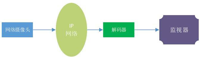
Figure 3: Network Camera IP Transmission System
At the monitoring center, the decoder directly receives the IP video in streaming format, decodes it, and outputs it to the monitor via an HDMI or other interface.
3. Test Solution
In response to the JTG2182-2020 standard, Beijing Doewe Technologies Co., Ltd. offers a fully compliant automated test system solution covering the CCTV test requirements within the standard. It supports all standard-required test pattern generation functions and various video transmission quality testing functions.
3.1 CCTV Monitoring Test System Vision Eye
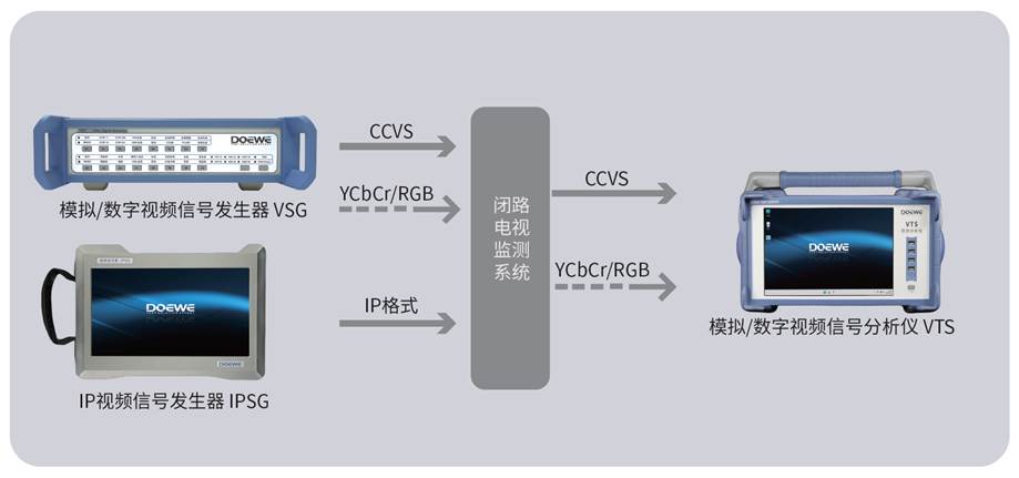
Figure 4: Vision Eye Test Connection Diagram
Description: The CCTV monitoring test system Vision Eye primarily includes: Analog/Digital Video Signal Generator (VSG), IP Video Signal Generator (IPSG), and Analog/Digital Video Signal Analyzer (VTE).
For the highway transportation industry, the system supports "Comprehensive Test Pattern" signal generation, integrating all test image signals required by the JTG2182-2020 standard. The system does not require switching test signals during the process and supports one-click testing, enabling simultaneous testing and display of results for all test metrics. Once the test system is set up, the overall test time generally does not exceed 10 seconds.
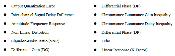
The system supports test items including but not limited to:
3.2 Traditional Analog Video Transmission System Test Solution
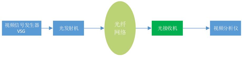
Figure 5: Traditional Analog Video Transmission System Test Solution
For testing traditional analog video transmission systems, a typical test setup is shown in Figure 5. The primary test equipment used are a Video Signal Generator (VSG) and a Video Analyzer (VTE). The VSG generates CCVS or YPbPr signals, which pass through the transmission system before being tested by the VTE.
For digitized HDMI video signal transmission, if the transmission link still uses an optical transmitter/receiver architecture, the testing principle is the same as for traditional analog video testing. However, the video signal generator and analyzer need to support the HDMI interface, and the video analyzer must internally perform D/A conversion.
3.3 IP Network Transmission System Test Solution
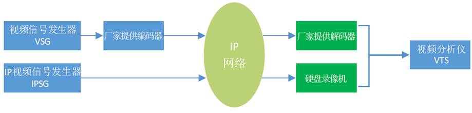
Figure 6: IP Network Transmission System Test Solution
For testing IP network video transmission systems, a typical test setup is shown in Figure 6. The signal generation equipment primarily consists of a Video Signal Generator (VSG) and an IP Video Signal Generator (IPSG). The signal analysis equipment primarily uses a Video Analyzer (VTE).
A standard VSG is used to generate CCVS, YPbPr, or HDMI signals. Manufacturer-provided encoders are then used to implement IP conversion and matching before transmission over the IP network. Correspondingly, the receiving end also requires the manufacturer-provided decoder to convert the IP data back into a form receivable by the VTE, which then performs the analysis.
If the signal generation device uses the IP Video Signal Generator (IPSG), it can directly generate IP video signals, eliminating the need for manufacturer-provided encoders for IP conversion and matching. After transmission over the IP network, the signal can be converted into an analyzable format by a Digital Video Recorder (DVR) and then transmitted to the VTE for analysis. Alternatively, it can be saved locally on the DVR's hard drive for subsequent analysis.
Given that different CCTV monitoring systems are built by different manufacturers, testing often requires coordination with various vendors to perform matching tests based on their specific encoders/decoders. This process can lead to various issues and may even necessitate on-site technical support from the manufacturers, making it cumbersome. Using the IPSG for signal generation avoids such problems. Additionally, the video signals output by the IPSG support the GB/T 28181-2016 protocol, eliminating concerns about matching issues with the monitoring center during transmission.
4. Core Test Equipment Introduction
4.1 Analog/Digital Video Signal Generator (VSG)
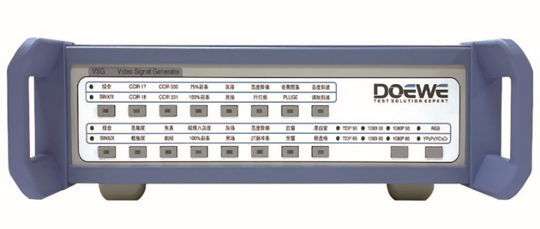
● Supports Analog Composite Video (CCVS) / Analog HD Component (YPbPr) & HDMI Output;
● Modular design, allowing configuration or upgrade as needed;
● Multiple standard test patterns, including specialized SD/HD Comprehensive Test Patterns for highway applications;
● Direct button settings for switching images and formats, offering convenient operation;
● SD signals support 720x576/50Hz, aspect ratio 4:3;
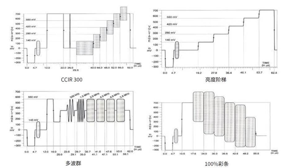
● SD Comprehensive Test Pattern includes CCIRL 7/18 /330/331, 75% Color Bars, SINX/X, 50% Flat Field, Red Field, 15KHZ Square Wave, and Silent Line signals;
● HD resolutions support 1080i/1080P, frame rates support 50Hz/60Hz;
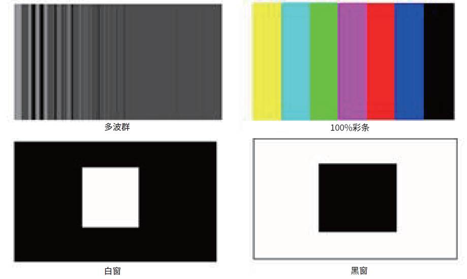
● HD provides Comprehensive Test Pattern, Multiburst, 100% Color Bars, Extreme Eight Grayscale, White Window, Black Window, Black & White Window, Checkerboard, White Field, Black Field, Jump Frame, and Smear Test Patterns valid under 1080i and 1080p formats.
4.2 IP Video Signal Generator (IPSG)

● The IPSG supports Gigabit Ethernet ports and can directly output standard video signals via these ports, with future expansion capability for optical port output;
● IP video output supports GB/T 28181-2016 protocol (Media Sender), RTSP protocol (Server side), and RTSP protocol (Client Announce push);
● Supports configuration of GB/T 28181-2016 standard parameters, including SIP Server ID, Domain, Address, Port, Password, Heartbeat Interval, and Concurrent Quantity;
● Supports configuration of RTSP Server parameters, including Start Port, Stream Start Name, and Concurrent Quantity;
● Supports configuration of RTSP Push Client parameters, including RTSP Push Address and Concurrent Quantity;
● The device supports functions for adding, saving, loading, and deleting test plans. Video output configurations can be saved, and loading a test plan directly imports the saved settings for testing;
● Video sources can be selected as H.264 encoded video files with the .mp4 suffix;
● Video sources can be static images, encoded into an output stream using H.264, with controllable parameters like resolution and bitrate;
● Supports simulating multiple (no less than 128) concurrent signal sources, bound to different ports, for emulating multiple camera terminals;
● The IPSG module features a touchscreen design.
4.3 Analog/Digital Video Signal Analyzer (VTE)
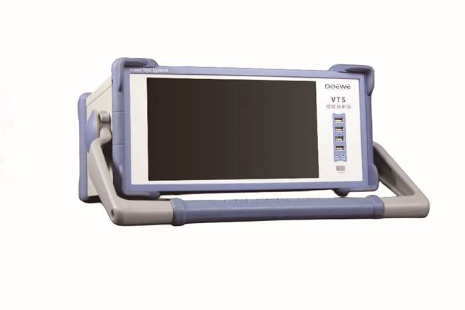
● Integrated design, specifically born for testing CCTV transmission channels in traffic applications;
● Supports metric testing for Composite Video Signals (CCVS) and HDMI video signals;
● Supports component video testing for HDMI interface inputs; can view HDMI interface video information;
● Component video analysis via HDMI input supports R/G/B and Y/Cb/Cr;
● Supports direct switching between different input modes; supports signal waveform display function, with test signal and test position setting/display capabilities;
● Supports importing test setup templates, one-click test execution, direct reading of all test results corresponding to JTG 2182 standard items, supports test result screenshot output;
● Composite Video Testing Supports: Video Output Amplitude, Luminance Waveform Distortion, Luminance-Chrominance Delay Difference, DG/DP, Luminance Non-Linear Distortion, Video Frequency Response, and Synchronization Characteristics;
● Component Video Testing Supports: Y Signal Input Amplitude, Cr Signal Input Amplitude, Cb Signal Input Amplitude, Non-Linear Distortion, Luminance Channel Linear Response, Signal Delay Difference, SNR, and other functions.
4.4 Typical Test Signals