1.Introduction
In recent years, with the rapid development of automated testing, structural health monitoring, intelligent manufacturing, new-energy equipment and other fields, data acquisition systems based on the PXIe platform have been increasingly used in engineering tests. As an open, modular and high-bandwidth test and measurement platform, PXIe offers the following typical advantages:
- High bus bandwidth and easily expandable channel count, meeting the requirements of multi-point, multi-physics simultaneous testing;
- Flexible module form factor that allows convenient integration of various acquisition cards for voltage, current, bridge circuits, acoustics, vibration and other signals;
- Together with host-side software and trigger/clock resources, it can realize automated testing under complex operating conditions.
Against this backdrop, test data are no longer simple single-channel or single-point recordings, but correlation analyses among multiple channels, multiple sensors and multiple physical quantities. This directly leads to a core question: how to ensure strict time alignment of data across all channels, i.e., the “synchronization” problem.
This article focuses on the synchronization between different channels on the same PXIe data acquisition card. It first discusses the importance of data synchronization and the consequences of asynchronous acquisition, and then takes a PXIe acquisition card as an example to analyze the basic principles and implementation methods of single-board multi-channel synchronization. The synchronization problem between different acquisition cards will be discussed separately in a subsequent article.

2.Importance of Data Synchronization
2.1 Requirements of Multi-Channel Test Scenarios
In practical engineering projects, multi-channel acquisition has long become the norm. For example, in structural vibration testing, multiple acceleration sensors must be acquired synchronously for modal analysis and mode-shape identification; in motor and power-electronics testing, voltage, current, speed, torque and other signals need to be acquired simultaneously for efficiency analysis and control-algorithm verification; in acoustics and noise testing, multiple microphone-array channels must be acquired synchronously for sound-source localization and beamforming; in tests of set-top boxes, communication equipment and other electronic products, power consumption, temperature and control signals need to be acquired synchronously for correlation analysis and fault localization.
These applications share a common feature: subsequent data processing is usually based on the time relationships between channels rather than on the absolute value of any single channel. Typical examples include calculating phase differences, transfer functions and cross-correlation functions; analyzing event sequences, such as “after a fault signal appears on one channel, the response delay on other channels”; performing spatial reconstruction (array measurements) and multi-sensor information fusion. If the time axes of the channels are misaligned or drifting, then even if the sampling accuracy on each individual channel is high, the overall test conclusions may still be wrong or even mutually contradictory.
2.2 From “Same Sampling Rate” to “Same Sampling Instants”
In engineering practice it is easy to encounter a misunderstanding: “as long as multiple channels are configured with the same sampling rate, they are synchronized.” In fact, even with the same sampling rate of 10 kS/s, if each channel has its own independent clock or is started independently, their sampling instants can have a fixed offset and may even gradually drift during the test. In this case, although the channels share the same average sampling interval, the timestamp of each sample point is not the same, and the acquisition is still asynchronous.
True multi-channel synchronization, in a strict sense, involves at least two levels:
1. Unified time reference: all channels share the same clock source or clocks that are phase-locked to a common reference;
2. Unified sampling start point and sampling cadence: sampling on all channels begins at the same instant and is driven by the same “sample clock”;
Only when both conditions are satisfied can we ensure that “the same sample index n corresponds to the same physical time t on all channels.”
3. Problems Caused by Asynchronous Acquisition
If, in a PXIe data acquisition system, the channels on the same acquisition card are not truly synchronized, the following problems may arise:
3.1 Errors in Multi-Channel Phase and Amplitude Analysis
In frequency-domain analysis, the phase relationships between channels are typically used to determine the system’s phase response, transfer functions and so on. If there is a time offset Δt between channels, then at frequency f an additional phase error will be introduced:
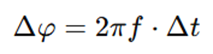
For high-frequency signals, even a very small time offset can be converted into a significant phase error, which in turn leads to inaccurate transfer-function estimation, incorrect judgments of system stability and modal-analysis results that deviate from the real situation. In transient analysis, time offsets will also cause the peaks of the same event on different channels to fail to line up, so that peak amplitudes, rising edges and other features cannot be extracted accurately.
3.2 Time Drift in Long-Duration Tests
If each channel relies on a non-phase-locked clock or on different clock sources, then as test duration increases, small frequency differences in the sampling clocks will accumulate into a large time drift. Waveforms that appear “roughly aligned” in the short term may, over time, show clearly separated sample sequences, leading to an inability to perform long-term trend analysis of different channels on a common time axis, distortion of long-term correlation analysis (for example between temperature and power consumption or between vibration and load), and difficulty in correcting such errors afterwards through simple interpolation.
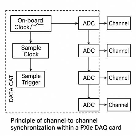
4 Basic Principles of Single-Board Multi-Channel Synchronization Based on PXIe
Within the PXIe architecture, a multi-channel data acquisition card is usually designed for “single-board multi-channel synchronization” at both hardware and driver levels. The basic idea can be summarized as follows: on the same card, provide all channels with a unified time reference, a unified sampling clock and a unified start trigger, so that their sampling instants are exactly aligned. The following subsections analyze several key aspects.
4.1 Unified Time Reference (On-Board Clock / Reference Clock)
A PXIe acquisition card typically has an on-board clock, for example a high-stability crystal oscillator providing a base frequency such as 10 MHz or 20 MHz. At the same time, a PXIe chassis can provide a system reference clock (for example a 10 MHz reference) through the backplane for the modules to phase-lock to. For single-board multi-channel synchronization there are generally two approaches:
1. All channels share the same on-board clock: all sampling-related clock signals (such as the sample clock and internal divided/multiplied clocks) are derived from the same base crystal via frequency division/multiplication; no channel has its own free-running oscillator, thus avoiding relative drift during long-term operation.
2. The acquisition card is phase-locked to the chassis reference clock: the on-board clock is locked, via a PLL, to the reference clock provided by the chassis. Although this mechanism is used more often for multi-card synchronization, it also helps improve the long-term stability of the time base for a single card.
Regardless of which method is used, the key point is that all channels on the acquisition card use a “common clock source”. A common clock ensures that the sampling period is exactly the same across all channels and lays the foundation for the subsequent “unified sampling instants”.
4.2 Unified Sampling Instants (Shared Sample Clock)
Once a unified time reference is established, a PXIe acquisition card usually also implements a unified sample clock to drive all of its sampling channels. There are two general architectures for this:
1. Multi-ADC simultaneous-sampling architecture: each channel is equipped with its own analog-to-digital converter (ADC), and all ADCs are driven by the same sample clock. At each sampling instant tn, all ADCs simultaneously sample their respective analog inputs and output digital results. This architecture achieves true “point-by-point simultaneous” sampling and is suitable for scenarios that place stringent requirements on phase and transient characteristics, such as vibration testing and acoustic arrays.
2. Multiplexed multi-channel + single-ADC architecture: multiple channels are routed in turn through analog switches/multiplexers to a single ADC. The overall sampling period is controlled by a unified sample clock, but the channels are scanned sequentially within each sampling period. For low-frequency, slowly varying signals (such as temperature or slowly changing voltages), this can be regarded as “quasi-synchronous”, but strictly speaking there is still a fixed time offset between channels.
In engineering practice, when strict synchronization is required (especially for phase analysis and array measurements), PXIe acquisition cards that support simultaneous sampling with multiple ADCs should be preferred, and this requirement should be clearly specified during system design and hardware selection.
4.3 Unified Start Trigger
Even if all channels share the same sample clock, if they start acquisition at different times there will still be a fixed offset on the time axis. Therefore, PXIe systems typically provide a unified start-trigger mechanism: in the driver configuration, multiple channels are grouped into the same “task”. The task does not start the sample clock and begin acquisition until it receives a “start acquisition” trigger signal (Start Trigger). Because all channels in the task share the same trigger source, the “first sample” on each channel corresponds to the same instant. This trigger signal can be either: a software trigger — the host computer issues a start command and the driver generates an internal trigger; or a hardware trigger — an external digital signal or a threshold event on some analog channel.
For single-board multi-channel synchronization, it is generally recommended to place all channels that need to be synchronized in the same acquisition task as far as possible, so as to avoid unnecessary timing differences caused by starting multiple tasks separately. If multiple tasks must be used, they should at least share the same hardware trigger source and be driven by the same sample clock.
DOEWE Technology has always been committed to delivering innovative, distinctive and reliable product solutions in the field of data acquisition. We understand that these elements are the cornerstone for enterprises to remain competitive in the market. For this reason, our inspiration for innovation comes from our customers’ real application needs, rather than from flashy but impractical product features. By continuously optimizing and enhancing our data-acquisition solutions, DOEWE Technology helps partners move toward a future of efficient and accurate testing. You are welcome to choose DOEWE Technology and open a new chapter in data acquisition together with us.