1 Introduction
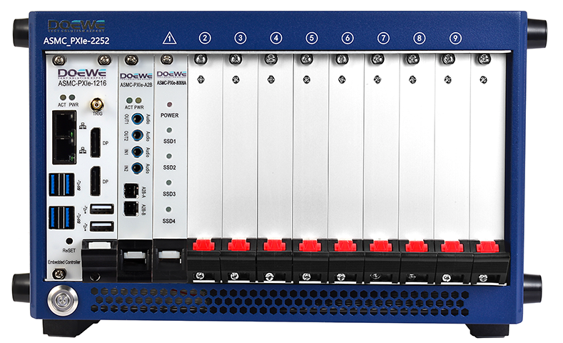
In the previous article, “Research on Single-Board Multi-Channel Synchronization Mechanism Based on PXIe”, we focused on how, within a single PXIe data acquisition card, unified time reference, unified sample clock and unified start trigger can be used to achieve strict time alignment of all channels. However, in real engineering projects the number of channels provided by a single acquisition card is often limited. As test scale and complexity continue to increase, users increasingly need to operate multiple, or even more than ten, PXIe acquisition cards simultaneously in order to obtain hundreds or even thousands of synchronized channels. In some complex systems, the acquisition cards may be distributed within a single chassis, across multiple chassis, or even in different racks, forming large-scale multi-point synchronized acquisition systems. In such cases, if we only maintain synchronization within each individual card while lacking a unified time reference and trigger mechanism between cards, then from a system perspective theoverall multi-channel measurement is still “fragmented” and cannot support rigorous system-level analysis.
Based on the PXIe platform, this article focuses on channel synchronization among multiple acquisition cards in the same PXIe chassis. It first introduces typical application scenarios and challenges of multi-card synchronization, then analyzes the system-level problems that may arise if only single-card synchronization is ensured while the cards themselves remain asynchronous, and finally discusses the basic principles and common implementation schemes of multi-card synchronization by making use of PXIe backplane resources. Issues of distributed time synchronization across chassis and racks will be addressed in future articles.
2 Typical Applications and Challenges of Multi-Card Synchronization
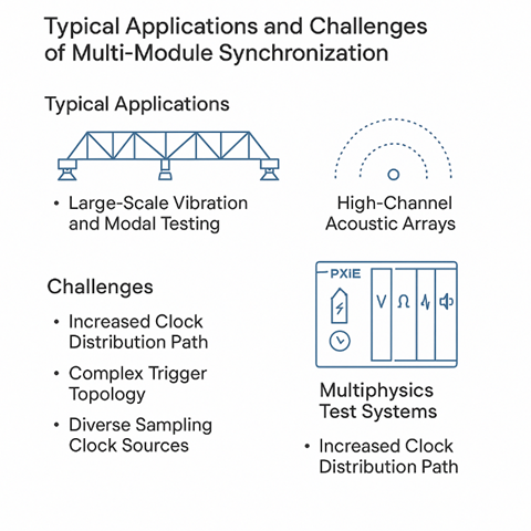
In engineering practice, multi-card synchronization typically appears in several representative application scenarios. Large-scale structural vibration and modal testing is one of them: in tests on large mechanical structures, complete vehicles, locomotives, wind-turbine blades or bridges, a large number of acceleration, strain and displacement sensors are often deployed, and a single acquisition card cannot meet the channel-count requirement, so multiple vibration acquisition cards must work together. Similar situations arise in high-channel-count acoustic arrays and noise testing. Large microphone arrays used for acoustic imaging, beamforming or sound-field reconstruction impose strict requirements on both the number of channels and phase consistency, so the sampling instants and start times of multiple acoustic acquisition cards must be tightly aligned. On the other hand, multi-physics joint test systems also rely heavily on multi-card synchronization. For example, when various acquisition cards for voltage, current, temperature, vibration and acoustics are integrated into the same PXIe chassis to perform multi-physics joint tests on motor drives, power-electronics devices or set-top-box assemblies, all different types of acquisition cards must share a common time axis in order to ensure the reliability of correlation analysis, causal analysis and event reconstruction. For multi-node parallel-analysis systems built around A²B and other bus protocols, the acquisition cards responsible for bus waveforms, protocol events and environmental signals must maintain a consistent time reference and trigger boundary, so that a particular frame error or node reconnection can be accurately linked to power fluctuations, vibration shocks and other physical factors.
Compared with single-board synchronization, multi-card synchronization faces greater challenges in engineering implementation. First, the clock-distribution path becomes significantly longer: the reference clock must travel from the chassis or timing module to each acquisition card, crossing backplane traces and even front-panel cables, so latency and jitter accumulate and amplify, placing higher demands on synchronization accuracy. Second, the trigger topology becomes more complex. Multiple acquisition cards may reside in different slots and listen to different PXI_TRIG lines or star-trigger resources, so choosing appropriately between bus triggers and star triggers, and minimizing trigger skew, is an important system-design consideration. Third, the sources of sample clocks are more diverse: some acquisition cards generate their sample clocks locally from the chassis 10 MHz reference clock, while others directly receive an external Sample Clock. When these approaches are mixed, an overall plan is required to avoid situations where the nominal frequencies are the same but their phase relationships are uncontrolled. Finally, in terms of configuration and management, engineers must configure the clock sources, trigger sources and division ratios of multiple cards in a unified way in software and establish a consistent time coordinate system; otherwise, one may encounter hidden problems where “the GUI settings look identical but the cards are in fact not synchronized”.
3 Problems Caused by Single-Card Synchronization but Multi-Card Asynchrony
If, in system design, only per-card synchronization of channels is ensured but clocks and triggers between cards are not managed in a unified way, then from an overall perspective the system will face several risks. First, significant errors are likely to occur in system-level phase and transfer-function analysis. In test scenarios such as structural vibration, acoustic arrays or motor drives, it is common to compute transfer functions and phase responses, cross-correlation and coherence functions across channels located on different cards, and even to further extract modal parameters or wavenumber vectors. If there is a fixed time offset Δt between two acquisition cards, an additional phase error Δφ≈2πf·Δt will arise at frequency f; errors in the high-frequency range will be amplified, manifesting as overall shifts of the transfer-function phase curves, deviations of modal-analysis results from their true values, and degraded beam steering, broadened main lobes or incorrect steering directions in acoustic arrays.
Second, it becomes easy to draw incorrect conclusions in event-sequence and causality analysis. In multi-physics joint test systems, engineers often need to answer questions such as: “Did a particular current surge occur before the protection action?” or “What is the time relationship between an A²B bus reconnection event and the vehicle-body vibration peak?” If these signals are distributed across different acquisition cards and those cards do not share a unified time reference, time-axis offsets between sampled data will lead to wrong judgments about event order, make time intervals between events incomparable to limits specified by standards, and make it difficult to accurately reconstruct complex fault processes or relationships among multiple events.
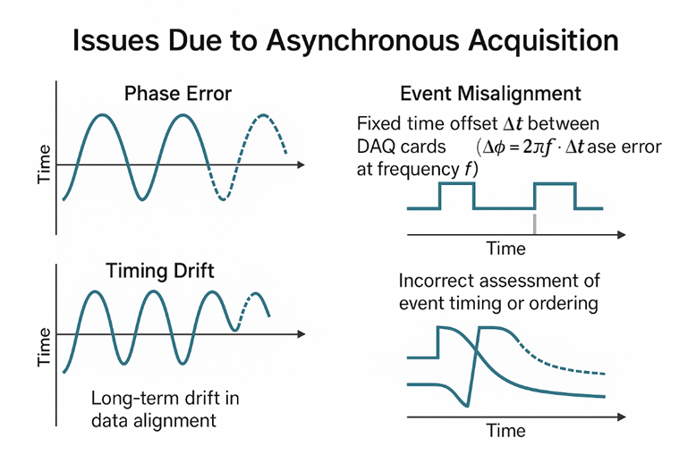
Third, in long-duration operation, cross-card time drift becomes even more serious. If each acquisition card relies on its own on-board clock, then even when the factory specifications are very good, tiny differences in frequency will still accumulate into obvious time drift in long tests. Initially, over time scales of a few seconds or tens of seconds, waveforms from channels on different cards may still appear roughly aligned, but when tests last for tens of minutes or several hours, the time axes of the channels have already diverged significantly. For applications such as durability tests and environmental-reliability tests that require long continuous operation, this means that long-term trends in temperature, power consumption and vibration collected across cards cannot be correlated on a unified time axis; even if one tries to realign the data afterwards by interpolation or resampling, only limited effectiveness can be achieved locally, and it is hard to cover the entire test process.
4 Basic Principles of Multi-Card Synchronization Based on PXIe Backplane Resources
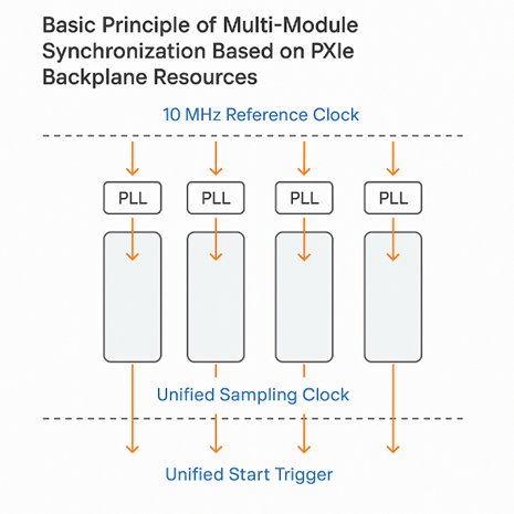
The PXIe standard reserves rich hardware resources on the chassis backplane for clocks and trigger signals, allowing multi-card synchronization to be implemented quite naturally within a chassis. Conceptually this can be summarized in three layers: first, a unified reference clock; second, a unified sample clock; and third, a unified start trigger. A typical PXIe chassis provides a 10 MHz reference clock PXI_CLK10 on the backplane, which is distributed in single-ended form to all slots and used either directly by traditional PXI modules or as the reference for a phase-locked loop (PLL). At the same time, a set of differential reference clocks, such as a 100 MHz differential clock, is also provided as a low-jitter differential time base for high-speed modules. The first step in multi-card synchronization is to lock the time base of each acquisition card to the same reference clock. Generally, the clock module inside each acquisition card will lock to PXI_CLK10 or to a PXIe differential clock via a PLL; alternatively, a dedicated timing and synchronization module can inject a high-stability reference clock onto the backplane for the acquisition cards to lock to. Once all cards use the same reference clock as their “master clock”, each card can synthesize its own sample clock from it while avoiding relative drift during long-term operation.
After the reference clock has been unified, the sample clocks between cards must also be unified. Common implementation methods include the following. One approach is to have each acquisition card, once locked to the same reference clock, locally synthesize its sample clock using the same division or multiplication ratio. With a properly designed PLL, this method is simple in terms of routing and can keep the frequencies and phase relationships between sample clocks highly consistent. In other systems, one acquisition card is selected as the master card for the sample clock. The master synthesizes the Sample Clock and distributes it to the other slave cards via dedicated backplane lines (such as PXIe_DSTARA/B) or front-panel coaxial cables; the slave cards then use the received Sample Clock as their own sample clock, thus ensuring physically aligned sampling instants. For systems with higher synchronization-accuracy requirements and larger channel counts, a dedicated Timing & Synchronization module can also be used as the clock master, directly providing a unified Sample Clock to multiple acquisition cards. The differential star-clock lines in PXIe (such as PXIe_DSTARA) play a crucial role in this process by offering a low-skew, low-jitter clock-distribution path, which forms an important physical foundation for high-precision multi-card synchronization.
After unifying the sample clocks, it is still necessary to ensure that all acquisition cards start acquisition from the same “initial point”; otherwise, even with perfectly identical sample clocks, there will still be a fixed offset on the time axis. For this reason, the PXIe backplane provides multiple trigger buses and star-trigger resources. For example, PXI_TRIG0–7 can serve as shared trigger buses: any one card can drive them while the others listen. Star-trigger resources such as PXI_STAR or PXIe_DSTARB route triggers from the timing slot to each peripheral slot with equal or effectively equal path lengths, helping to reduce trigger skew. In a typical multi-card start-up procedure, engineers configure the tasks on each acquisition card in software to listen to the same backplane trigger source, such as PXI_TRIG0 or PXI_STAR, and then generate a single “start acquisition” trigger on the master card or timing module. This trigger reaches all acquisition cards simultaneously through the backplane, and each card starts its sample clock and begins acquisition when it receives this trigger event. When very high start-up synchronization accuracy is required (for example, nanosecond-level), star-trigger resources are usually preferred over ordinary trigger buses in order to reduce propagation differences introduced by different slot positions.
5 Typical Implementation Schemes for PXIe Multi-Card Synchronization
From a systems-engineering perspective, the above principles lead to several common implementation schemes for multi-card synchronization. A relatively simple approach is to make full use of the chassis reference clock and unified configuration: all acquisition cards are locked to the PXI_CLK10 reference clock, the same sampling rate is configured for each card in software, the driver internally synthesizes the sample clocks based on the unified reference clock, and a single PXI_TRIG line is used to realize unified start-up. This scheme is easy to implement and low in cost, and is suitable for applications with moderate synchronization requirements and total channel counts on the order of tens to about one hundred.
When test scale further increases and synchronization-accuracy requirements become more stringent, a more common approach is to insert a dedicated Timing & Synchronization module in the timing slot. This module injects a high-quality reference clock and a programmable Sample Clock onto the backplane, and distributes the clock and trigger signals to the acquisition cards via differential star-clock and star-trigger resources such as PXIe_DSTARA/B and PXI_STAR. This scheme is somewhat more complex in hardware, but it provides better phase consistency and smaller trigger skew, and is widely used in large-scale vibration arrays, acoustic arrays and precision measurement systems.
In cases where backplane resources are limited or only a small number of cards need to be synchronized locally, a Master/Slave scheme using front-panel clock and trigger connections can also be adopted. Typically, engineers select one acquisition card as the master and send its Sample Clock from a front-panel clock-output connector to the clock-input connectors of the other cards, while using front-panel trigger input/output to build the start-trigger chain. In this way, even when backplane trigger resources are insufficient, a flexible synchronization topology can still be constructed on the front-panel side. In real projects, DOEWE Technology chooses among or combines the above schemes according to the user’s channel scale, synchronization-accuracy requirements, chassis configuration and cost constraints, striving to strike a reasonable balance between cost, complexity and performance.
Through extensive engineering practice, DOEWE Technology has built a complete hardware and software solution around PXIe multi-card synchronization. On the hardware side, we offer PXIe acquisition cards, timing modules and controllers for vibration, acoustics, motors, power electronics and other application scenarios. On the software side, a unified test platform centrally manages clock sources, trigger sources and task configurations, and provides tools for verifying synchronization performance. At the project-delivery level, we tailor the synchronization topology and implementation details to the user’s specific operating conditions to ensure that verification results obtained in the laboratory can be reliably transferred to complex field environments. In future work, we will further explore time-synchronization schemes across chassis, across racks and even across distributed nodes, in order to provide scalable synchronization capabilities for larger-scale data acquisition systems.