1、Introduction
In cutting-edge applications such as new energy batteries, power semiconductors, and flexible electronics, materials are often subjected to complex conditions such as fast pulses, voltage spikes, or large current impacts. Under such conditions, their conductive paths, thermal behavior, and even failure mechanisms can change dramatically with transient electrical conditions. Relying solely on steady-state DC or low-frequency testing may easily underestimate the risks and performance limits of materials in real-world working environments. By systematically studying the voltage-current dynamic characteristics, researchers can capture the response curves of materials within the microsecond to second time domain, thereby quantifying related properties such as conductivity degradation and thermal stability. This provides accurate data for formulation iteration, structural optimization, and reliability assessment.
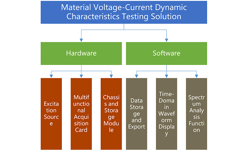
This solution aims to provide a voltage-current dynamic characteristic testing solution for materials. By applying specific waveform voltage or current excitation to the material using an excitation source, the data acquisition system collects changes in voltage, current, and other signals after the material to analyze its dynamic characteristics. By accurately capturing voltage and current signals, users can monitor the material's response under different electrical conditions in real-time, helping them gain a deeper understanding of the material's performance under actual working conditions. This process is crucial for evaluating properties such as conductivity, thermal stability, and pressure resistance, and provides scientific data support for material optimization and design. The overall structure diagram of the testing system is as follows:
2、Specific Testing Solution
2.1 Testing System Principle
The system consists of two parts: hardware and software. The hardware part includes the excitation source and the data acquisition system. The excitation source provides programmable waveform outputs, with waveform types, signal frequencies, amplitude, and DC bias all freely editable according to customer requirements. The data acquisition system collects voltage signals in real-time through a voltage acquisition module connected in parallel across the material under test. It also monitors current changes by using a current acquisition module connected in series in the circuit.
Through the data acquisition and analysis system, users can obtain precise voltage and current data, with the ability to view real-time time-domain waveforms and perform spectrum analysis. The data is saved using high-speed storage methods to ensure data integrity and security. The software part provides an integrated data acquisition and analysis platform that supports real-time viewing, storage, and export of the collected voltage and current signals. The built-in time-domain waveform display and spectrum analysis functions help users immediately identify anomalies or spectral characteristics in the signals. Additionally, the system allows for the export of test results as needed for subsequent offline analysis or report creation.
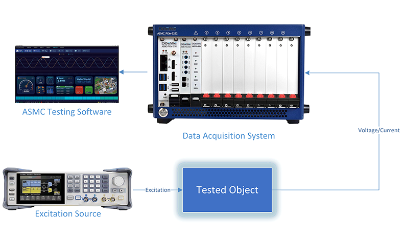
Through the collaboration of hardware and software, this system enables synchronized measurement and analysis of the material's voltage-current dynamic characteristics. During testing, any waveform generator first injects the set excitation signal (with programmable frequency, amplitude, and bias) into the input of the material under test. The voltage acquisition channel is connected in parallel across the material, recording voltage changes in real-time. The current measurement channel is connected in series with a current acquisition module (or precision shunt resistor) in the circuit to simultaneously capture the current flowing through the material. All channel data is collected by the PXIe chassis and unified by ASMC software for synchronized timing. The corresponding time-domain waveform and spectrum analysis can be displayed instantly and stored at high speed. In this way, users can obtain the complete voltage-current response curve of the material under different electrical excitations, accurately assessing its conductivity, dynamic impedance, and energy consumption performance, providing a reliable basis for material optimization and design. The test flowchart is as follows:
2.2 Introduction to Data Acquisition and Testing Analysis Software ASMC
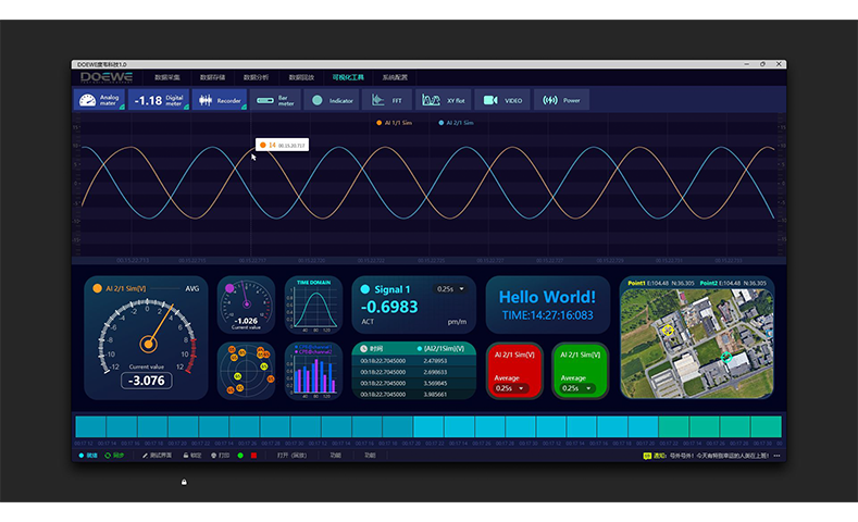
The data acquisition and testing analysis software ASMC offers a variety of powerful features, providing comprehensive support for the voltage-current dynamic characteristics testing of materials. The software supports high-precision acquisition of voltage and current, allowing continuous measurement of the voltage across the material and current in the circuit, ensuring full-channel synchronization to maintain data accuracy and consistency. The software also provides real-time waveform display functionality, enabling instant presentation of time-domain waveforms during the acquisition process, helping testers observe the material’s response at any time, enhancing the real-time nature and operational convenience of the test.
In addition, the ASMC software includes an automatic data saving feature, which allows the sampled data to be written in real-time to local high-speed storage, ensuring the integrity of data over long testing periods and preventing frame loss. After the experiment is completed, the software supports exporting data into multiple common file formats (such as CSV, XLSX, etc.), simplifying offline analysis and report creation.
The software interface provides flexible parameter adjustment capabilities, allowing users to set the sampling rate and range for each channel in real time, and supports dynamic changes to the signal acquisition type to meet various testing needs. Additionally, the ASMC software includes built-in spectrum analysis and power calculation modules, using FFT and power algorithms to perform frequency-domain analysis of the acquired signals, and output statistical results such as average power and peak values, providing strong support for subsequent in-depth data analysis and decision-making.
With these features, the ASMC software fully meets the various demands of material electrical performance testing, ensuring the efficiency and accuracy of data acquisition, analysis, and report generation during the testing process. The software interface diagram is shown below:
2.3 Core Parameters of the Testing System
This testing system features several key parameters that ensure its efficient and accurate operation in various testing scenarios. The system provides 8 configurable input channels, supporting signal types such as voltage, IEPE, current, strain gauge, RTD, etc., offering flexibility to meet different measurement needs. The signal types include voltage (±2 mV ~ ±100 V), IEPE (±100 mV ~ ±10 V), strain gauges (±1 mV ~ ±1000 mV), resistance (10 Ω ~ 30 kΩ), current (±30 mA), MSI counting/thermocouple/LVDT, and more. The system’s maximum sampling rate is 0 S/s ~ 5 MS/s per channel, ensuring the capture of high-frequency signals. The sampling resolution is 24 bits for the range of 0 ~ 2 MS/s, and 18 bits for the range greater than 2 ~ 5 MS/s to accommodate varying precision requirements.
The system's analog bandwidth is 2 MHz, satisfying the needs for common test signal frequency ranges, and it provides channel-to-chassis isolation of ±350 V DC, ensuring stability in complex environments. The rated input withstand voltage (to ground) is 33 V RMS / 46.7 V PEAK / 70 V DC, providing strong anti-interference capabilities. The reference calibration port uses an SMB interface (dedicated to the LEMO version), facilitating system calibration and reference. The system is also equipped with 512 MB of onboard data buffering, ensuring efficient and continuous data storage.
To achieve data synchronization or external bus acquisition, the system offers a high-speed CAN 2.0 interface. Users can optionally select the AOUT-8 version, which provides isolated analog output, supporting output ranges of ±5 V, ±10 V, or ±30 mA to meet various testing needs. In terms of input connectors, the system offers 8-channel 0B-LEMO connectors (or 4-channel D-SUB/BNC, depending on the version), ensuring diverse connectivity options.
In terms of environmental conditions, the system operates within a temperature range of 0 ℃ ~ +45 ℃, with a storage temperature of -20 ℃ ~ +70 ℃. It supports working humidity of 10% ~ 80% (non-condensing) and storage humidity of 5% ~ 95%, adapting to a variety of environmental conditions.
Regarding reliability, the system’s MTBF (Mean Time Between Failures) is 196,187 hours for the 2M sampling rate version and 93,843 hours for the 5M sampling rate version, reflecting its high stability. For power consumption, the system’s typical power consumption in different modes is as follows: Voltage mode ≤ 15 W; IEPE mode 15 W / 19 W; Bridge mode 18 W / 21 W. This testing system is a PXIe 3U single-slot module, compact in size, making it suitable for space-constrained testing environments.
These core parameters ensure that the system operates stably during high-precision and high-efficiency testing, meeting a wide range of testing needs and providing reliable data acquisition and analysis support.
3、Solution Advantages and Features
1. Synchronized Voltage/Current Measurement: A single PXIe acquisition card provides 8 configurable voltage or current channels.
2. High Precision/Sample Mode Switching: The sampling rate maintains a 24-bit resolution in the range of 0–2 MS/s, and automatically switches to 16-bit resolution when the rate is increased to 2–5 MS/s. This ensures high precision for steady-state testing while meeting the high-speed requirements for transient shock measurements.
3. Multi-Range Integrated Input: The same module can simultaneously acquire multiple signal types, including ±2 mV ~ ±100 V voltage, ±30 mA current, IEPE, strain gauges, RTD, etc., eliminating the need to switch between acquisition modules.
4. 2 MHz Bandwidth + Channel Isolation: The high analog bandwidth, along with full-channel/channel-to-chassis isolation, effectively suppresses common-mode noise and ensures data integrity in high-frequency and large common-mode scenarios.
5. Arbitrary Waveform Excitation and Free Editing: The waveform type, frequency, amplitude, and DC bias can be script-set; once the waveform is determined, it can be sent with one click, reducing the preparation and iteration time for test cases.
6. Hardware Clock-Level Synchronization: The acquisition modules share the PXIe clock, achieving millisecond-level alignment of voltage parallel and current series channels, providing a high-precision time reference for power calculations and spectrum analysis.
7. High-Speed Data Storage Guarantee: Acquired data is written in real-time to a high-speed storage card in the chassis, meeting the needs of long-duration, high-frequency testing, and ensuring the integrity of the raw waveform data.
8. One-Click Data Export and Report Generation: After acquisition, the ASMC software can export raw voltage and current data, as well as spectrum analysis results, to common file formats with one click and automatically generate a test report, facilitating subsequent archiving and sharing.
3、Solution Advantages and Features
1、Synchronized Voltage/Current Measurement: A single PXIe acquisition card provides 8 configurable voltage or current channels.
2、High Precision/Sample Mode Switching: The sampling rate maintains a 24-bit resolution in the range of 0–2 MS/s, and automatically switches to 16-bit resolution when the rate is increased to 2–5 MS/s. This ensures high precision for steady-state testing while meeting the high-speed requirements for transient shock measurements.
3、Multi-Range Integrated Input: The same module can simultaneously acquire multiple signal types, including ±2 mV ~ ±100 V voltage, ±30 mA current, IEPE, strain gauges, RTD, etc., eliminating the need to switch between acquisition modules.
4、2MHz Bandwidth + Channel Isolation: The high analog bandwidth, along with full-channel/channel-to-chassis isolation, effectively suppresses common-mode noise and ensures data integrity in high-frequency and large common-mode scenarios.
5、Arbitrary Waveform Excitation and Free Editing: The waveform type, frequency, amplitude, and DC bias can be script-set; once the waveform is determined, it can be sent with one click, reducing the preparation and iteration time for test cases.
6、Hardware Clock-Level Synchronization: The acquisition modules share the PXIe clock, achieving millisecond-level alignment of voltage parallel and current series channels, providing a high-precision time reference for power calculations and spectrum analysis.
7、High-Speed Data Storage Guarantee: Acquired data is written in real-time to a high-speed storage card in the chassis, meeting the needs of long-duration, high-frequency testing, and ensuring the integrity of the raw waveform data.
8、One-Click Data Export and Report Generation: After acquisition, the ASMC software can export raw voltage and current data, as well as spectrum analysis results, to common file formats with one click and automatically generate a test report, facilitating subsequent archiving and sharing.
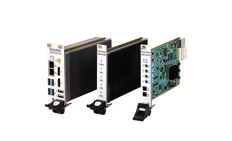
4、Hardware Core Product Introduction
4.1 Multifunctional Acquisition Card
The ASMC-PXIe-4054 multifunctional acquisition card is designed specifically for voltage-current dynamic characteristic testing. It integrates 8 programmable input channels in a single-slot 3U PXIe form factor, which can be switched as needed for high-precision voltage (±2 mV ~ ±100 V), current (±30 mA), IEPE, strain gauge, or RTD thermistor measurements. The same card can also synchronize with auxiliary signals such as thermocouples and LVDT. The maximum sampling rate for each channel is 5 MS/s, with 24-bit resolution maintained from 0-2 MS/s, and 18-bit resolution from 2-5 MS/s. The card is equipped with a 2 MHz analog bandwidth and 512 MB of onboard buffering, enabling frame-loss-free recording of transient shocks and steady-state drifts. The channel-to-channel and channel-to-chassis isolation rating reaches ±350 V DC, with a rated withstand voltage of 33 V RMS, ensuring clean waveforms even in high common-mode noise environments. The card also reserves one high-speed CAN 2.0 port for synchronized external bus data acquisition. The AOUT-8 version provides isolated ±5 V / ±10 V or ±30 mA analog output, making it convenient for closed-loop control or calibration. The card operates in a temperature range of 0 °C to +45 °C and has a storage temperature range of -20 °C to +70 °C, with a typical power consumption of ≤ 15 W (voltage mode). It is the core component for achieving synchronized sampling of multiple physical quantities, power calculation, and spectrum analysis within a PXIe chassis. Core Parameters of the Acquisition Card:
1、Input Channels: 4-8 channels (configurable as: voltage, IEPE, current, strain gauge, RTD, etc.)
2、Signal Range: Voltage ±2 mV ~ ±100 V; Current ±30 mA; Resistance 10 Ω ~ 30 kΩ
3、Maximum Sampling Rate: 5 MS/s (per channel)
4、Resolution: 24-bit at 0 ~ 2 MS/s; 18-bit at > 2 ~ 5 MS/s
5、Analog Bandwidth: 2 MHz
6、Isolation Rating: Channel-to-channel / Channel-to-chassis ±350 V DC
7、Onboard Buffer: 512 MB
8、High-Speed Interface: PXIe 3U single-slot, integrated 1 × CAN 2.0 synchronization port
9、Output Option: AOUT-8 version provides isolated ±5 V / ±10 V / ±30 mA analog output
10、Operating Temperature Range: 0 °C ~ +45 °C; Storage -20 °C ~ +70 °C
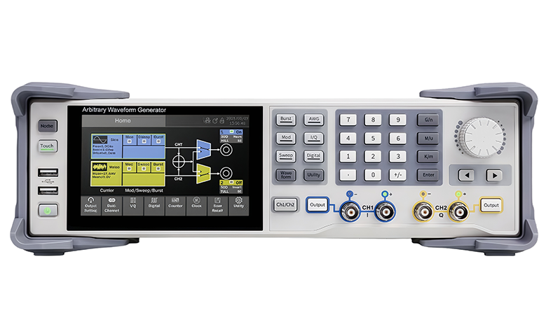
4.2 Arbitrary Waveform Generator
The excitation source uses the SDG7052A arbitrary waveform generator, which features dual-channel differential/single-ended output, an analog bandwidth of 500 MHz, and a 14-bit DAC. The instrument can generate point-by-point arbitrary waveforms within a sampling rate range of 0.01 Sa/s–2.5 GSa/s, with a single-channel waveform depth of up to 512 Mpts. It supports segment editing and seamless playback. It provides minimum pulse width of 1 ns and 500 ps rise/fall time pulses, with built-in AM/FM/PM/FSK/ASK and other analog and digital modulation functions, frequency sweeping, and pulse train capabilities. The generator can also produce PRBS, Gaussian Noise, and 16-bit high-speed digital bus signals. The maximum single-channel output amplitude is 24 Vpp, with the ability to superimpose a ±12 V DC bias, meeting the need for wide-range excitation. The channels can be coupled, tracked, or serve as modulation sources for each other, making it easier to construct complex dual-channel waveforms. The front panel features a 5" touchscreen and USB/LAN/external trigger interfaces, supporting both local and remote (SCPI) control modes, making it a flexible and programmable high-performance excitation core for material voltage-current characteristic testing. The core parameters of the arbitrary waveform generator are as follows:
1、Output Channels: Dual-channel differential/single-ended output, 14-bit vertical resolution
2、Analog Output Bandwidth: 500 MHz (SDG7052A model specification)
3、D-A Sampling Rate: 5 GS/s; Arbitrary waveform sampling rate 0.01 Sa/s – 2.5 GS/s, with waveform depth up to 512 Mpts/channel
4、Maximum Output Amplitude: 24 Vpp, with the ability to superimpose ±12 V DC bias, meeting wide-range excitation requirements
5、Minimum Pulse Performance: 1 ns pulse width, 500 ps rise/fall time, suitable for high-speed transient testing
6、Built-in Modulation and Frequency Sweeping: Supports AM/FM/PM/FSK/ASK analog/digital modulation and frequency sweeping, pulse train functions
7、Digital/Bus Output (Optional): 16-bit LVTTL/LVDS, maximum rate of 1 Gbps
8、Interface Configuration: USB Host ×3, USB Device, LAN (VXI-11/Telnet/Socket), external trigger/reference clock In/Out, etc.
9、Human-Machine Interaction: 5-inch 800 × 480 touchscreen, supports WebServer remote control and SCPI automation
10、Environmental and Dimensions: Operating temperature 0 °C – 50 °C; Overall dimensions 338 mm × 113 mm × 369 mm, weight ≈ 4.4 kg