1. Application Scenario
In modern manufacturing, CNC machine tools, as precision machining equipment, are crucial for product quality due to their processing efficiency and accuracy. Cutting tools, as key components of CNC machine tools, directly impact machining efficiency and workpiece surface quality. Traditional cutting tool quality assessment methods typically rely on manual inspection and machining experiments, which are not only time-consuming and labor-intensive but also struggle to ensure consistency and accuracy in evaluation. Especially in high-precision and high-efficiency machining fields, requirements for tool quality are becoming increasingly stringent. Therefore, a rapid and accurate method for assessing tool quality is particularly important.
This test solution aims to utilize vibration analysis technology combined with high-precision data acquisition (DAQ) equipment to achieve rapid assessment of CNC machine tool cutter quality. The method evaluates the damping effectiveness of the cutter by monitoring its vibration response under impact excitation and using characteristic parameters of the vibration signal, thereby determining its quality level.
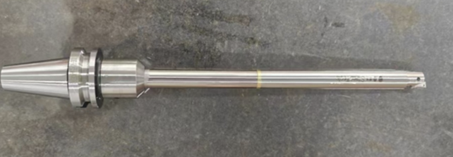
Figure 1 CNC Machine Tool Cutter Display
2. Introduction to the Test Method
2.1 Test Principle
When a cutter is subjected to external force excitation, it vibrates. The vibration signal contains information about the cutter's material, structural design, and manufacturing process. Damping performance is one of the important indicators for measuring cutter quality. Good damping effectiveness means the cutter can absorb and dissipate vibration energy more quickly when subjected to external forces, thereby maintaining the stability and precision of the machining process. We can leverage this characteristic to quickly and accurately distinguish the quality of cutters based on the different durations of vibration for cutters with varying damping effectiveness. The test block diagram is shown below:
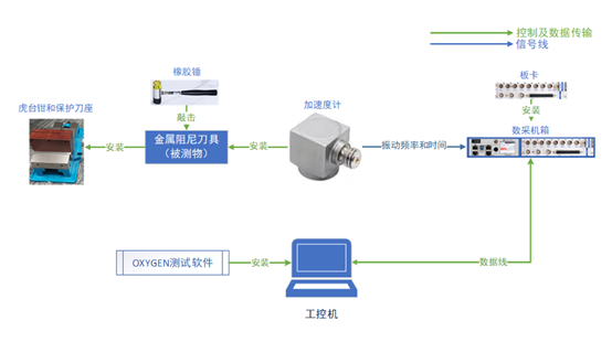
Figure 2 Cutter Damping Test System Block Diagram
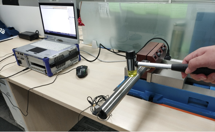
Figure 3 Physical Setup of Cutter Damping Test
2.2 Test Steps
1.Preparation Phase:
● Connect the equipment according to the block diagram above to set up the test environment.
● Select the cutter to be tested, ensuring its surface is clean and free of oil contamination.
● Install the vibration sensor (accelerometer) on the cutter, ensuring it is tightly coupled and will not detach during vibration.
● Secure the cutter using a tool holder and vise to prevent displacement or loosening during the test.
2.Excitation Phase:
● Use an impact hammer or other non-destructive excitation method to strike the cutter, causing it to vibrate.
● The impact should be quick and of moderate force, ensuring the vibration signal generated by each impact is repeatable.
3.Data Acquisition Phase:
● Start the DAQ equipment to begin acquiring the cutter vibration signal.
● Record the time-history data of the vibration signal, including key parameters such as vibration amplitude, frequency, and decay rate.
4.Data Analysis Phase:
● Use data analysis software to preprocess the acquired vibration signal and obtain the vibration waveform diagram of the tested cutter.
● Evaluate the damping effectiveness of the cutter based on the waveform decay characteristics in the vibration waveform diagram, thereby determining its quality level.
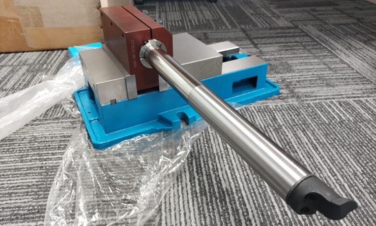
Figure 4 Cutter Fixation Method Display
2.3 Evaluation Criteria
The damping effectiveness of the cutter is judged based on the duration of vibration decay in the vibration signal. Better damping effectiveness results in faster vibration decay, indicating higher cutter quality. Specific evaluation criteria can be set according to actual needs, such as setting the time required for vibration to decay to a certain threshold as the judgment basis. Alternatively, a reference standard can be established first by measuring the vibration duration of a cutter with good damping effectiveness identified through machining experiments. The vibration duration of other tested cutters can then be compared against this standard to judge their quality. This comparative experiment requires the tested cutters and the standard cutter to be of identical specifications.
3. Test Results (Using 32mm Diameter Damping Cutter Test as an Example)
To better demonstrate the test results and enhance the reliability of this solution, we conducted vibration tests on a group of cutters using a comparative experiment approach. First, a set of cutters of the same specification but with different damping effectiveness (one with good damping, one with poor damping) were identified through machining experiments. After securing both cutters, the same location on each was selected as the impact point, keeping other variables consistent. Multiple impacts were performed, and multiple sets of data were acquired. Repeating the acquisition process ensured the reliability and consistency of the results. The test results were then displayed as waveform diagrams using the device software for more intuitive analysis of the differences between the two cutters. Below are the waveform diagrams and analysis process for the two cutter test results.
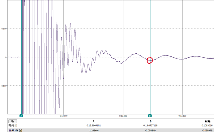
Figure 5 Vibration Waveform of Cutter with Poor Damping Characteristics
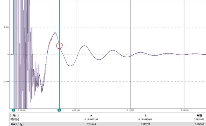
Figure 6 Vibration Waveform of Cutter with Good Damping Characteristics
i Image Analysis: From the two images, it can be seen that a comparison was made under identical conditions. The selected time interval was approximately 100ms for both, and the waveform amplitude range was set to ±1g to ensure a completely identical test environment. The positions marked by red circles represent the moment when the high-frequency vibration components disappear. Although both vibration-damping rods reached the state where high-frequency vibration disappeared at this position, the rod with poor damping characteristics required significantly longer decay time than the one with good damping characteristics. This indicates its weaker ability to suppress high-frequency vibrations. The rod with good damping characteristics eliminated the high-frequency components and returned to a stable state in a shorter time, demonstrating superior vibration damping performance.
ii High-Frequency Vibration Components: From the above waveform diagrams, high-frequency vibration components manifest as rapidly changing waveforms, while low-frequency components show slower-changing waveforms. The circled position marks the moment when high-frequency vibration components completely disappear. At the beginning of the test, the amplitude of the high-frequency components was very large, far exceeding that of the low-frequency components. This is because the high-frequency components mainly originate from the transient impact vibration caused by striking the cutter, while the low-frequency components are induced by the natural vibration of the test platform and are not the focus of this test. Therefore, we are only concerned with the decay of high-frequency vibrations to assess the cutter's vibration damping performance.
iii Data Table: The test data results are recorded and analyzed in tabular form. These data allow for a more intuitive observation of the differences in vibration damping performance between different cutters.
Table 1 Test Result Data Table
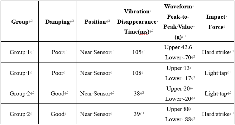
iv Summary: Through comparative analysis of the high-frequency vibration disappearance time, waveform peak-to-peak value, and vibration waveform characteristics, cutters with good damping performance can be effectively distinguished from those with poor performance: Cutters with good damping performance exhibit a shorter high-frequency vibration disappearance time and a smoother low-frequency vibration waveform, indicating excellent vibration damping characteristics. Cutters with poor damping performance show a longer high-frequency vibration disappearance time and unstable waveforms, indicating inferior vibration damping effectiveness. This analysis method based on high-frequency vibration disappearance time and waveform characteristics can help accurately judge and distinguish the vibration damping effectiveness of cutters.
4. DAQ Equipment Introduction
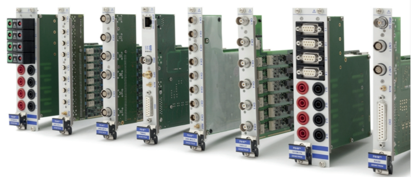
Figure 7 Test Board Module Display
4.1 Equipment Overview
The high-precision DAQ equipment used in this test solution is paired with highly sensitive vibration sensors. The DAQ equipment consists of a data acquisition module (functional board), acquisition & analysis software, and a control host. This equipment features high precision, high sensitivity, and strong real-time capabilities, enabling accurate capture of cutter vibration signals and real-time processing and analysis.
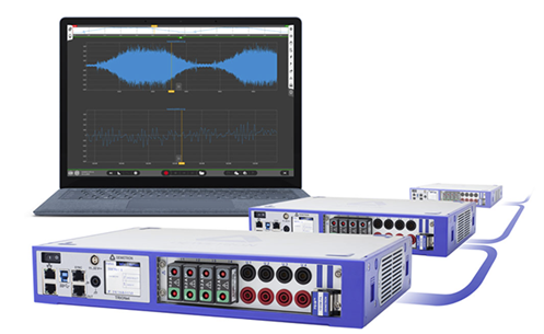
Figure 8 Physical View of DAQ Equipment
4.2 Equipment Features
● High-Precision Acquisition: Paired with high-precision accelerometers, it can accurately capture high-frequency components of cutter vibration, ensuring data authenticity and integrity.
● Real-Time Processing Capability: Equipped with powerful built-in signal processing algorithms, it can analyze vibration data in real-time and extract key characteristic parameters such as vibration waveform, time, and decay.
● User-Friendly Interface: Provides an intuitive operation interface and data analysis tools, facilitating quick understanding of test results and decision-making by operators.
● Scalability and Compatibility: Supports connection of various sensor types. Different sensors can be paired with different signal acquisition modules. By selecting and installing different acquisition modules in the control host, data acquisition for different signal types can be achieved. Easily integrates into existing production monitoring systems for seamless data transfer and in-depth analysis.
● Data Storage and Export: Provides high-capacity data storage functionality, supports data export and sharing, facilitating subsequent data analysis and report generation.
4.3 Equipment Application Scenarios
● Environmental Adaptability Testing: The DAQ system can test equipment under extreme temperature and humidity conditions, such as thermal management testing, mechanical and seismic vibration testing, electromagnetic interference immunity testing, etc., ensuring product stability and reliability in harsh environments. Suitable for various environmental adaptability tests.
● Bench Testing: DAQ equipment is widely used in bench testing for automotive, aerospace, and other fields, ensuring the reliability of critical components under demanding conditions. The DAQ system can be easily integrated with test benches, enabling data transmission and remote control through various interfaces (e.g., CAN).
● Vibration and Noise Testing: By using IEPE sensors and order analysis functions, DAQ equipment can perform noise and vibration order analysis and modal testing on rotating machinery and structures.
● High-Precision Signal Acquisition: The DAQ module supports high-precision acquisition of various signal types including voltage, current, vibration, noise, and thermocouples, suitable for precision testing in scientific research, industry, defense, and other fields.
In summary, this test solution utilizes vibration analysis technology and high-precision DAQ equipment to achieve rapid assessment of CNC machine tool cutter quality. This method offers advantages such as simple operation, accurate evaluation, and high efficiency. It is suitable for quality assessment of various types of CNC machine tool cutters, providing an effective solution for intelligent and refined manufacturing in the industry.
Beijing Doewe Technologies Co., Ltd. owns the independent brand "Doewe Instruments," focusing on the R&D, production, and sales of electronic test & measurement instruments/test systems. After years of development, the company's business covers multiple fields, establishing several divisions: Broadcasting/AV Division, Transportation Division, University & Research Institute Division, and Consumer Electronics Division. We relentlessly pursue innovation in test and measurement technology, dedicated to technology development, application software services, and test & measurement solution research. To this end, we have established the "Doewe Technologies Center" in Beijing and the "Qingdao Technical Service Center" in Qingdao. Relying on the Beijing headquarters and related technology centers, the company is gradually establishing a nationwide service and sales network, including Northeast Office, East China Office, Southwest Office, and South China Office, enabling us to provide timely pre-sales and after-sales service.
Contact Phone: +86 010-64327909
Website: https://www.doewe.com
Email: info@doewe.com
Address: Room 1821, Building 2, Sobao Business Center, No. 16 Nan San Huan Xi Lu, Fengtai District, Beijing, China