1.Solution Overview
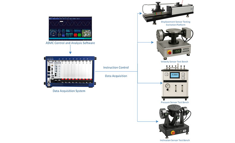
This solution aims to provide a complete automated testing solution for various sensors, including pressure sensors, displacement sensors, velocity sensors, inclination sensors, and more. The solution integrates test benches, data acquisition systems, and software control platforms, enabling efficient and accurate testing of multiple sensors to ensure their performance meets the relevant usage standards.
For different types of sensors, the test platform uses professional hardware excitation equipment for simulation and testing. Pressure sensor testing employs an automatic pressure source that can simulate different pressure values and perform automated testing. Displacement sensor testing uses a high-precision moving platform to ensure accurate measurement of displacement sensors. Velocity sensors are tested using a rotating platform, where angular velocity sensors can also be converted to calculate linear velocity. Inclination sensors are simulated and tested using an inclination table. All sensors are closely connected to the data acquisition system, which transmits the measurement results in real time and provides the necessary excitation signals to the sensors.
The data acquisition system, as the core module, is responsible for receiving data from each sensor and providing the necessary control signals to ensure that the excitation signals are accurate and stable. The controller inside the system, equipped with testing software, not only manages the overall system control but also performs real-time data analysis, automatically determines the sensor’s performance, and generates detailed test reports. This automated solution integrates test benches with data acquisition systems, significantly improving testing efficiency, reducing human intervention, and providing reliable test results to ensure the quality and reliability of sensors.
This solution, through its highly integrated hardware and software control system, achieves comprehensive and precise sensor testing management, providing strong support for sensor production, R&D, and maintenance. The system architecture diagram is as follows:
2. System Description
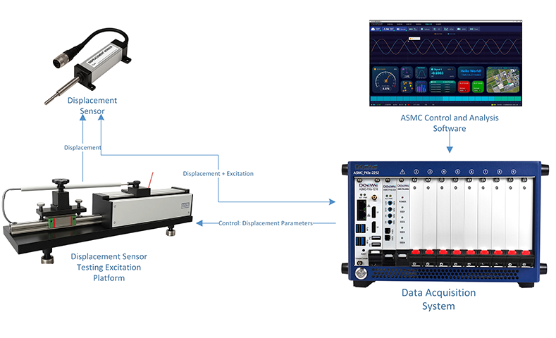
2.1 Testing System Principles
Through the collaboration of hardware and software, this platform can synchronize the measurement and analysis of the output of the tested sensor and the reference quantity during the calibration process. During the test, the displacement sensor to be tested is first fixed on the dedicated test bench; the test bench's drive and displacement feedback cables are connected to the PXIe data acquisition system. The ASMC control and analysis software is installed in the chassis controller, which sends commands such as displacement stroke and velocity to the test bench via the output channel, while simultaneously acquiring the sensor's voltage/current signals and displacement reference quantities of the test bench through the acquisition channel. The software performs closed-loop control, waveform display, and index calculation online, and the results are immediately stored and can be exported. When switching to other test benches such as pressure, inclination, or velocity, only the mechanical structure and sensor need to be replaced, while the signal lines and control logic remain unchanged. The boards are modular and pluggable, and electrical and software channels are automatically mapped, requiring no rewiring or secondary development. The test bench switch can be completed in a few minutes, allowing flexible expansion from single physical quantity verification to multi-quantity calibration. The testing flowchart is as follows (taking the displacement sensor test bench as an example; the only difference between different test benches is the test bench structure and the sensor being tested, while the wiring connections and specific control methods remain the same):
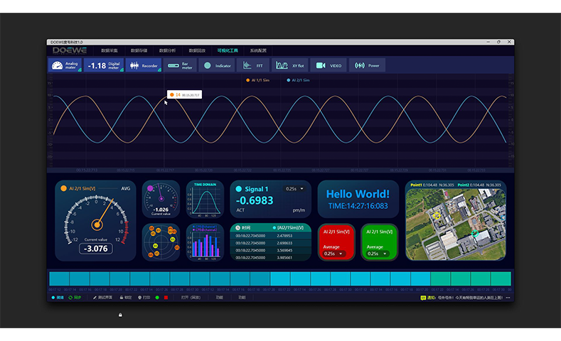
2.2 ASMC Testing Software Introduction
The ASMC Control and Analysis Software is installed on the PXIe controller, integrating device management, process control, and data analysis. The software is responsible for driving the board, configuring channels, and managing data flow. Users can set excitation signals, voltage/current sampling frequencies, and environmental parameters all within the same interface. The acquisition process allows for real-time monitoring of sensor outputs, with all raw data being synchronized to storage and dynamically visualized for immediate adjustments. The system supports one-click mode switching, automatic process execution, recording each response, and generating standardized inspection records.
The built-in analysis module can evaluate signal stability, response time, and other indicators, providing a health status conclusion. After testing, the software automatically generates a report containing raw data, analysis results, and evaluation opinions, and supports export in formats such as Excel and PDF.
The software can also perform zero drift and sensitivity analysis for pressure sensors, plot real-time displacement-output characteristic curves for displacement sensors, and evaluate return errors and linearity. For inclination sensors, it can set and stop any angle between 0° and 360° and generate linear error curves. The software architecture is flexible and configurable, meeting current automated sensor testing needs, while also enabling quick expansion to new sensors and testing scenarios, providing efficient, reliable, and traceable automated testing support for the entire platform. The software schematic is shown below:
3. Advantages of the Solution
1. Comprehensive Sensor Testing Capability: This solution supports testing of various sensors, including pressure sensors, displacement sensors, velocity sensors (angular velocity and linear velocity), and inclination sensors, ensuring that comprehensive testing needs for different sensors can be fulfilled on a unified platform.
2. High Automation and Efficiency: By utilizing automated hardware devices such as automatic pressure sources, moving platforms, and rotating platforms, combined with the automatic data transfer and control of the data acquisition system, manual intervention is greatly reduced, improving testing efficiency and the accuracy of test results.
3. Flexible Control and Monitoring: The close integration between the test bench, data acquisition system, and control software allows for flexible control of the entire system. Users can adjust testing parameters according to actual needs, monitor sensor performance in real-time, and ensure the stability of test conditions.
4. Improved Sensor Quality and Reliability: Through the automated testing process, each test condition can be precisely controlled, ensuring that every parameter of the sensor meets the standards, which improves production quality and long-term reliability of the sensors.
5. Accurate Data Analysis and Report Generation: The accompanying software system can perform real-time data analysis, automatically determine the quality of the sensor, and generate detailed test reports. This reduces human error while providing more reliable quality monitoring methods.
6. Intelligent Software Empowerment: The accompanying ASMC testing software collects and monitors sensor outputs in real-time, automatically manages the testing process, evaluates the sensor’s health status, and generates standardized reports with a single click. It supports export in formats such as Excel and PDF, significantly enhancing testing visualization, data traceability, and decision-making efficiency.
7. Support for Customization and Expansion: The testing system can be customized and developed according to customer needs, offering flexible expansion of features to meet diverse requirements in different application scenarios.
4. Hardware Product Introduction
4.1 Data Acquisition Module
4.1.1 Overview of Data Acquisition Module
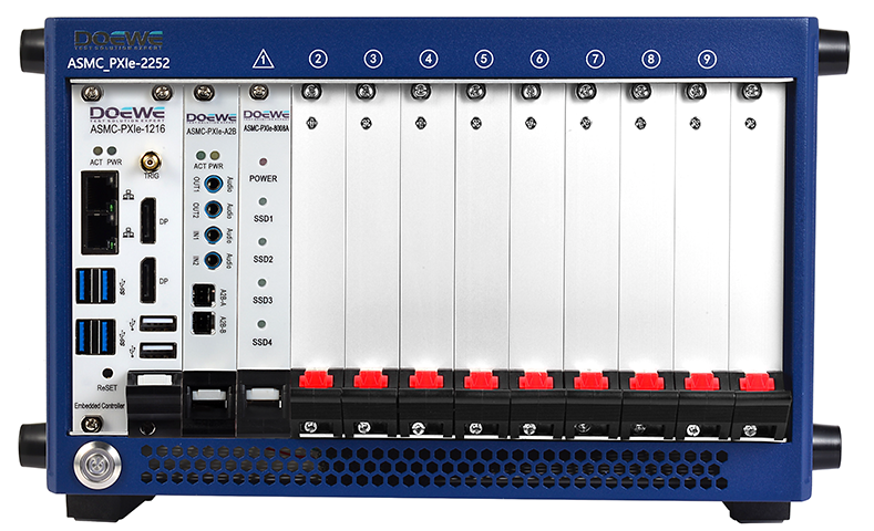
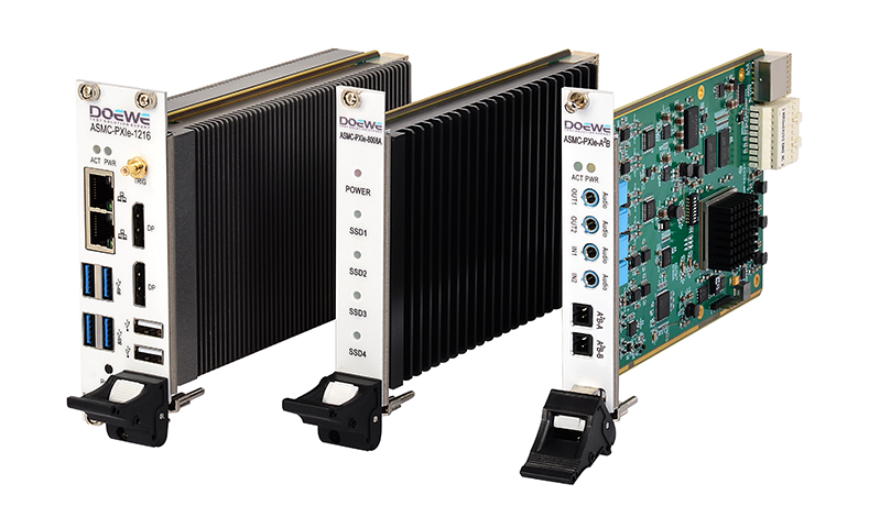
The control-storage, acquisition, and power supply modules are integrated into the same chassis based on the PXIe modular architecture. This system combines the ASMC PXIe 2252 high-bandwidth hybrid backplane chassis, PXIe 1216 embedded controller, and PXIe 8016 high-speed storage card to achieve device scheduling, data processing, and high-speed caching. The chassis provides regulated power supply, enhanced heat dissipation, and intelligent monitoring, supporting multi-chassis star synchronization to ensure long-term stable operation. The controller includes a high-performance processing unit and PCIe high-speed switching channels, and it monitors power consumption and temperature in real time to ensure the accuracy and reliability of data processing. The storage card uses large-capacity technology with low-latency writing, which can handle multi-channel high-load acquisition without issue.
The chassis also accommodates a single-slot data acquisition and sensor power supply board, which can simultaneously perform sensor excitation, high-speed acquisition of analog signals (voltage/current/frequency), and digital bus signal acquisition. The board features a built-in programmable power supply and IEPE constant current source, enabling real-time power supply monitoring. The analog section employs a high-speed and synchronized dual architecture to balance transient capture and high-precision measurement, while the digital section supports multi-protocol expansion to simplify wiring and synchronization design. The overall solution is highly modular, easy to maintain on-site, and expandable for future needs, meeting the complex sensor platform's requirements for performance, reliability, and upgrades. A product schematic of the control and storage modules is shown below:
4.1.2 Key Parameters of the Data Acquisition Module:
ASMC PXIe 2252 Chassis
• 1 system slot + 1 timing slot + 7 hybrid slots, system bandwidth 24 GB/s, single-slot 8 GB/s
• Built-in 600 W industrial power supply and enhanced heat dissipation; operating temperature: −20 ℃ to +70 ℃ / 10% to 90% RH
• Provides 10 MHz clock I/O, supports multi-chassis synchronization
ASMC PXIe 1216 Controller
• Intel® i7-6820EQ (2.8 GHz, Turbo Boost 3.5 GHz), 16 GB RAM (expandable to 32 GB)
• 512 GB SSD, local bus bandwidth up to 24 GB/s, supports P2P direct connection and real-time power/temperature monitoring
• Dual-slot 3U structure, operating temperature: 0 ℃ to +50 ℃
ASMC PXIe 8016 High-Speed Storage Card
• NVMe solid-state storage (up to 16 TB), PCIe x8 interface
• Continuous read/write bandwidth > 6 GB/s, onboard switch chip supports data passthrough and energy consumption monitoring
• Operating temperature: 0 ℃ to +50 ℃
Sensor Power Supply Board
• Programmable DC 5-24 V, ≤ 300 mA per channel; 24 V/4 mA IEPE constant current source
• Real-time power-on and undervoltage monitoring, unified regulated power supply
Analog Signal Acquisition Board
• General high-speed: ≤ 32 single-ended or 16 differential, 16 bit, 500 kS/s, ±10 V programmable range
• Synchronous dynamic: 8 channels, 24 bit, 8 S/s to 102.4 kS/s, built-in anti-aliasing filter and AC/DC coupling
• Data written directly to storage, single-slot sustained bandwidth 8 GB/s
Digital/Bus Signal Acquisition Board
• 16 isolated RS-485 DI, +6V to +30V high level; 1200-115,200 bps adjustable
• Plug-and-play support for MT/T 899-2000 NRZ and Modbus RTU, expandable to CAN, UART, Ethernet
• Shared PXIe 10/100 MHz clock for analog and digital acquisition with nanosecond-level synchronization; field-replaceable BNC/Lemo/M12 connectors
4.2 Sensor Testing Platform
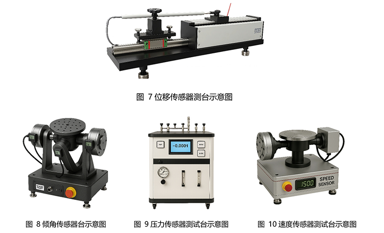
To ensure the high efficiency and accuracy of various sensors (such as pressure sensors, displacement sensors, velocity sensors, and inclination sensors) in automated testing, the system integrates professional test benches. Each test bench is designed for precise measurement and control of specific physical quantities, working in conjunction with the data acquisition system to provide real-time data transmission and analysis functions.
Displacement Test Bench: This test bench has a testing range from 0 to 1200 mm, with a positioning resolution of ≤0.1 mm and a testing accuracy of ±0.5 mm. It allows for precise displacement measurements and supports 5 equidistant measurement points within the range, ensuring that the performance of the displacement sensor at different positions is uniformly validated.
Pressure Test Bench: The pressure test bench has a testing range from 0 to 100 MPa, with a reading resolution of 0.01 MPa and a testing accuracy of ±0.1 MPa. This bench supports multi-point pressure calibration (including 0%, 25%, 50%, 75%, 100% full scale) as well as pressure stability testing. It can observe sensor output drift during pressure hold testing, ensuring the reliability and accuracy of the pressure sensor.
Inclination Test Bench: This test bench offers a rotational range from 0° to 360°, with a minimum step of 0.01° and a combined uncertainty of ±0.1°. It supports arbitrary angle setting and stopping from 0° to 360°, and can perform angular scanning (5 measurement points within the range). This design fully verifies the precision of the inclination sensor at different angles, ensuring its accuracy in practical applications.
Velocity Test Bench: The velocity test bench has a testing range from 0 to 10,000 r/min (approximately 0 to 15 m/s), with a resolution of 1 r/min or 0.01 m/s, and a combined error of ±1% FS. This test bench is suitable for high-speed rotating sensors, enabling precise evaluation of their response characteristics and accuracy.
These highly integrated test benches play a crucial role in the sensor testing process. When combined with the data acquisition system and ASMC testing software, they implement the entire process from sensor performance validation to automated data processing, ensuring the efficiency and accuracy of test results. A schematic diagram of the test benches is shown below: