1. Introduction
In FM stereo broadcasting systems, the 38kHz residual component of the S signal refers to the residual 38kHz subcarrier component that is not completely suppressed in the stereo composite signal (MPX). The modulation of this component onto the main carrier directly affects stereo separation, audio signal purity, and broadcast coverage quality, making it one of the key indicators for evaluating FM transmitter performance.
According to the International Telecommunication Union standard ITU-R SM.1268-1 and the People's Republic of China Radio, Film and Television Industry Standard GY/T 154-2000 Technical Requirements and Measurement Methods for FM Broadcasting Transmitters, the 38kHz residual component modulation products of FM transmitters must be controlled within specified thresholds. This applies to production acceptance, daily operation and maintenance, and performance calibration of FM broadcasting transmitters at all levels.
Professional modulation analyzers (such as the RWC2500A Plus) feature high-precision 38kHz residual component measurement capabilities. Their low-noise local oscillator design (<-130dBc@1GHz) and high signal-to-noise ratio (FM: 75dB Typ.) enable accurate capture of weak residual signals, providing reliable technical support for index detection. Precise control of the 38kHz residual component's impact on main carrier modulation is a core element in ensuring FM stereo broadcast signal quality.
2. Common Problems
1. Residual Component Exceeding Standards: Excessive 38kHz residual components can lead to degraded stereo separation and left/right channel crosstalk. Main causes include aging of the transmitter's stereo encoder filter circuits, improper balance adjustment, or MPX signal path interference. Solutions involve calibrating encoder filter parameters, replacing aging components, and optimizing signal path shielding design.
2. Insufficient Measurement Accuracy: Ordinary test equipment struggles to distinguish between the 38kHz residual component and normal modulation signals, easily causing misjudgment. Professional equipment supporting dedicated residual 38kHz measurement functions is required, such as the RWC2500A Plus, which features specialized measurement modules and standard-compliant algorithm models.
3. Legacy Equipment Functional Limitations: Early industry equipment like FMAB lacks precise 38kHz residual component measurement functions, features complex operation, and has been discontinued for many years. The RWC2500A Plus, specifically designed for FM broadcast testing, directly displays residual component modulation ratios through a visual interface and can replace legacy equipment.
4. Environmental and Link Interference: Electromagnetic interference in the test environment and RF link impedance mismatch can introduce false residual signals. Ensure the test environment is well shielded, RF cable impedance meets the 50Ω standard, and perform link calibration before measurement.
5. Lack of Equipment Calibration: Long-term transmitter operation causes performance drift in encoders and modulators, and test equipment accuracy degradation also affects results. Regular calibration of transmitters and test equipment should be performed according to the GY/T 154-2000 standard to ensure measurement baseline consistency.
3. Measurement Principles and Methods
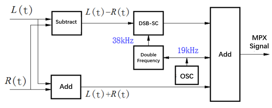
Based on FM stereo principles, the composite stereo signal mainly consists of three components: the M signal (L+R), the S signal (L-R), and a 19kHz pilot signal. As shown in the figure below, the 38kHz signal only acts on the S signal. Therefore, by turning off the pilot, making the left and right channels out-of-phase, and applying the same signal, the stereo signal retains only the S signal.
The standard measurement method for the 38kHz residual component is as follows:
5.2.6Measurement of the modulation of the main carrier by the residual 38 kHz component of the modulated s signal
5.2.6.1The measurement block diagram is shown in Fig 7.
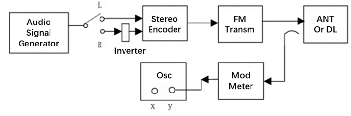
Fig 7 Block diagram for measuring the modulation of the main carrier by the residual 38 kHz component of the stereo broadcast modulated s signal
5.2.6.2Measurement Method
a) Turn off the pilot signal. Apply a 1 kHz signal simultaneously to the L and R (via the inverter, with no amplitude change) inputs of the encoder, adjusting the modulation to 90%. The signal applied to the Y-axis of the oscilloscope is the s signal (M=0); measure its peak-to-peak amplitude.
b) Remove the modulation signal. The oscilloscope will now display the residual subcarrier (i.e., leakage). Measure its peak-to-peak amplitude. The modulation degree of the main carrier by the residual subcarrier component is calculated as:
20lg(E’/E) (dB)
E′ —— Leakage amplitude (peak-to-peak)
E —— Amplitude of the modulated s signal (peak-to-peak)
The core equipment used in this article's measurement method is the RWC2500A Plus. Its 38kHz residual component testing method references the standard measurement approach. For specific equipment information, please visit www.doewe.com.
3.1 Equipment Connection
3.2 Test Procedure
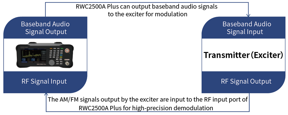
The RWC2500A Plus features a modulation analysis module, audio analysis module, and baseband audio signal output module. When measuring the 38kHz residual component, we need to use the baseband audio signal output module and modulation analysis module. Input the baseband audio signal into the transmitter's audio input port. After the transmitter modulates it into a broadcast signal, connect through a load and TEST signal to the RF signal input interface of the RWC2500A Plus, and use the modulation analysis module for analysis. Before testing, press the FREQ button to set the center frequency, ensuring the RWC2500A Plus matches the transmitter frequency, and turn off the transmitter's pilot signal.
3.2.1 Baseband Audio Signal Generation
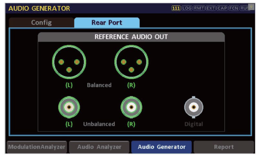
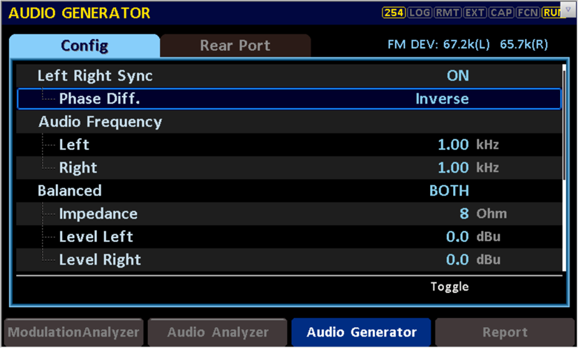
1. When using the RWC2500A Plus's baseband audio signal generation module, first select Rear Port in the Audio Generator interface. In this interface, you can quickly adjust the required audio output interface (Balanced/Unbalanced/Digital). After selection, proceed to the next step.
2.In this step, users can adjust the audio signal level and frequency, as well as the phase (in-phase/out-of-phase) of the left and right channels. During testing, adjust the left and right channels to be out-of-phase to retain the S signal. Audio signals are typically 1kHz. After setting the frequency, you can adjust the audio level in this interface. While adjusting, observe the upper right corner to ensure FM DEV(L)(R) is around 67.5kHz in FM mode.
3.2.2 Audio Analysis
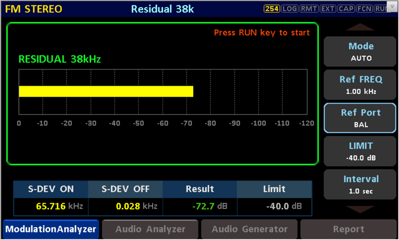
Enter the Residual 38k interface from the Modulation Analyzer's pull-up menu. Set Mode to AUTO on the right side of the interface, REF FREQ to 1kHz, and Ref Port to UNBAL/BAL/DIG according to the connected interface. Press RUN in the right button area, wait a few seconds, and read the test value at Result.
4. Core Equipment: RWC2500A Plus
4.1 Functional Overview
The RWC2500A Plus is a professional broadcast modulation analyzer primarily used for AM/FM transmitter testing, capable of single-unit comprehensive testing of RF parameters, modulation performance, and audio-level metrics.
The device can demodulate AM/FM (mono and stereo) in real-time, measuring carrier power, frequency deviation, AM modulation depth, FM frequency deviation, and pilot signal-related parameters. The device supports real-time output of demodulated audio signals. It features audio generation functionality that can output baseband audio signals, supporting independent settings for left/right channel levels and frequencies, with digital (balanced) and analog (balanced/unbalanced) audio output interfaces. The device has audio analysis capabilities to analyze demodulated baseband audio signals, supporting frequency-domain and time-domain analysis to display audio spectrum and waveform.
The RWC2500A Plus can directly analyze key broadcast transmitter metrics such as carrier parameters, audio distortion, audio SNR, audio frequency response, and stereo audio separation through its multifunctional combination, achieving transmitter metric testing with a single instrument to meet broadcasting industry transmitter testing requirements.
4.2 Product Features
• Supports high-precision AM/FM demodulation and parameter analysis, including stereo FM
• Fully replaces the industry-standard FMAB product
• Local oscillator frequency accuracy up to 1ppb, SNR: AM: 70dB (Typ.), FM: 75dB (Typ.)
• Can demodulate and output baseband audio, supporting balanced/unbalanced/digital interfaces
• Can display RF spectrum in real-time, and spectrum/waveform of demodulated audio
• Supports audio analysis to measure distortion, SNR, frequency response, and separation
• Supports audio generation to output single-tone or sweep signals with multiple interface options
• Supports custom upper/lower limits for test items, with real-time alerts for out-of-limit metrics
• Supports test results overview and data export, one-click report generation
• Color touchscreen and button collaborative operation
4.3 Performance Specifications
RF Performance
- Frequency Range: 500kHz~30MHz (AM), 76MHz~108MHz (FM)
- Frequency Resolution: 1Hz
- Input Power: -30dBm~30dBm (Permitted), -20dBm~20dBm (Calculated)
- Power Measurement Error: <0.5dB, Typ.
- Low Noise Local Oscillator: <-130dBc@1GHz, Typ.
- 10MHz Reference Signal Stability: 1ppb, aging <1×10⁻⁹/day
- Frequency Measurement Error @100MHz: <20Hz
Audio Performance
- Reference Audio Output Frequency Range: 20Hz~20kHz
- Reference Audio THD: <0.02%
- Reference Audio Frequency Response: Max: ±0.1dB
- De-emphasis Options: 50/75µs
- Left/Right Channel Level Difference: ≤0.1dB
- Measurement SNR: AM: 70dB (Typ.), FM: 75dB (Typ.)
- Measurement Isolation: 50dB
Interfaces
- RF Signal Input Interface: 1 N-type female connector
- Demodulated Audio Output Interface:
- Balanced: 2 XLR connectors (L, R)
- Unbalanced: 2 BNC connectors (L, R)
- Digital: 1 BNC connector (AES/EBU)
- Baseband Audio Output Interface:
- Balanced: 2 XLR connectors (L, R)
- Unbalanced: 2 BNC connectors (L, R)
- Digital: 1 BNC connector (AES/EBU)
- 10MHz Reference Clock Port:
- Input: 1 BNC type (50Ω)
- Output: 1 BNC type (50Ω)
- Digital I/O:
- LAN: RJ45
- RS232: USB-C type (VCOM)
Other Specifications
- Display: 5-inch LCD (800×400)
- Operating Temperature: 5~40°C
- Dimensions: 250×110×348mm
- Weight: 5kg