1.Introduction
Signal-to-Noise Ratio (SNR) is a core technical indicator for evaluating broadcast transmitter signal quality, defined as the ratio (in decibels, dB) of useful audio signal power to noise power at the transmitter output. This parameter directly determines signal transmission purity—the higher the SNR value, the weaker the masking effect of noise on effective information, resulting in clearer sound from receiver demodulation without interference such as static or background noise. Conversely, if SNR fails to meet standards, it leads to audio distortion, decreased signal recognition, and severely impacts the listener experience.
In the broadcasting industry, SNR is a key assessment criterion throughout the transmitter's entire lifecycle, requiring compliance with specific metrics during production acceptance, daily operation and maintenance, and regulatory broadcasting reviews. For example, according to broadcasting industry test specifications, medium-wave AM broadcast transmitters typically require SNR ≥ 60dB, and FM broadcast transmitters require SNR ≥ 60dB. These standards are crucial for ensuring mutual non-interference between different transmitters and maintaining transmission order within broadcast frequency bands.
Achieving accurate SNR measurement requires professional test equipment with stable performance—ordinary test instruments with inadequate noise control will introduce additional interference and distort measurement results. The RWC2500A Plus Broadcast Modulation Analyzer features high-precision local oscillator frequency of 1ppb and measurement SNR of 70dB (Typ.) in AM mode and 75dB (Typ.) in FM mode, effectively avoiding errors introduced by the test equipment itself and accurately capturing weak noise in transmitter output signals, providing reliable data support for AM/FM broadcast transmitter SNR detection.
Simultaneously, the device complies with existing relevant test standards, adapting to wide frequency ranges of 500kHz–30MHz (AM) and 76MHz–108MHz (FM), meeting test requirements for medium/short-wave AM transmitters and FM transmitters above 1kW (including 1kW). It is a suitable test tool for production, acceptance, and operation and maintenance segments in the broadcasting industry.
2.Common Problems
1、Large measurement result deviations:May be caused by insufficient SNR of the test equipment itself, poor interface connection contact, or improper measurement bandwidth settings. Solutions include using high-SNR test instruments like the RWC2500A Plus, checking connection status of balanced/unbalanced interfaces, and standardizing measurement bandwidth parameters per industry standards.
2、Environmental interference affecting tests:Electromagnetic interference and power supply fluctuations in the test environment introduce additional noise, causing SNR measurement distortion. Control the test environment within 5–40°C operating temperature range, use voltage regulators to ensure stable power supply, and stay away from strong electromagnetic interference sources.
3、Equipment aging causing metric drift:Aging of transmitter amplifier circuits/filter components or performance degradation of test instruments causes abnormal SNR measurement fluctuations. Perform regular maintenance and calibration of transmitters, conduct performance verification of test equipment, and update/replace when necessary.
4、Non-standard operation procedures:Incorrect audio signal parameter settings or wrong demodulation mode selection affect test accuracy. Strictly follow standard test procedures, use the RWC2500A Plus audio generation module to output standard test signals, and ensure demodulation mode matches transmitter type (AM/FM).
3.Measurement Method
This article's measurement method uses the RWC2500A Plus as the core device. For specific equipment information, please visit www.doewe.com.
3.1 Equipment Connection
3.2 Test Procedure
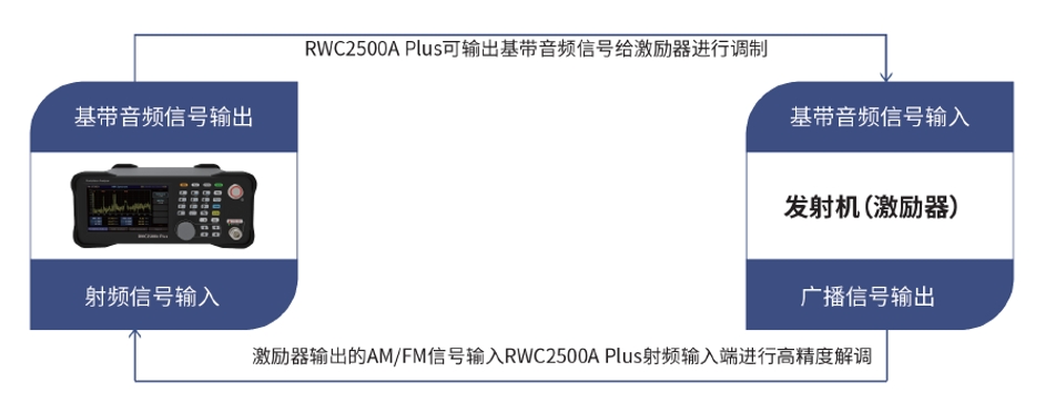
The RWC2500A Plus features a modulation analysis module, audio analysis module, and baseband audio signal output module. For SNR measurement, we need to use the baseband audio signal output module to feed the baseband audio signal into the transmitter's audio input port. After the transmitter modulates it into a broadcast signal, connect it through a load and TEST signal to the RWC2500A Plus RF signal input interface, then analyze using the modulation analysis module. Before testing, press the FREQ button to set the center frequency, ensuring the RWC2500A Plus matches the transmitter frequency.
3.2.1 Baseband Audio Signal Generation
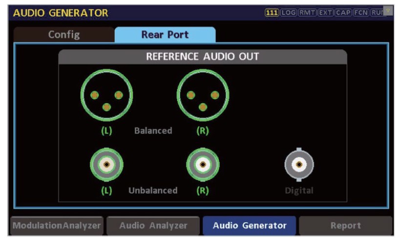
1. When using the RWC2500A Plus baseband audio signal generation module, first select Rear Port in the Audio Generator interface. This interface allows quick adjustment of the required audio output interface (balanced/unbalanced/digital). After selection, proceed to the next step.
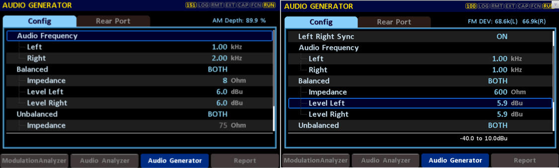
2. In this step, users can adjust the audio signal level and frequency. For modulation testing, a 1kHz audio signal is typically used. After setting the frequency, adjust the audio level in this interface. While adjusting, observe the upper-right corner: in AM mode ensure AM Depth is around 100%; in FM mode ensure FM DEV(L)(R) is around 67.5kHz.
3.2.2 Audio Analysis
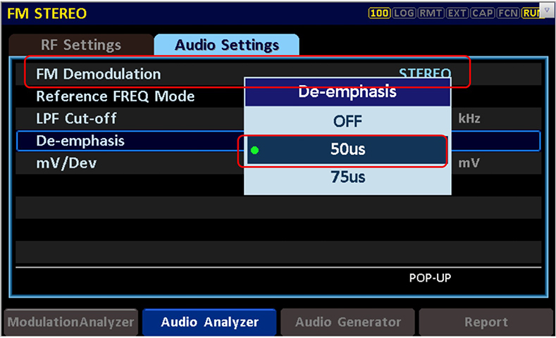
1. For FM transmitters, enter the Audio Settings interface from the Audio Analyzer dropdown menu. Set FM Demodulation to STEREO and De-emphasis to 50μs to match the transmitter's pre-emphasis parameters.
2. After configuration, select the SNR interface from the dropdown menu. Set Mode to AUTO, REF FREQ to 1kHz, and Ref Port to UNBAL/BAL/DIG based on the connected interface. Press RUN in the right button area and wait a few seconds to read the SNR test value in the Result field.

4.Core Equipment: RWC2500A Plus
4.1 Functional Overview
The RWC2500A Plus is a professional broadcast modulation analyzer primarily used for AM/FM transmitter testing, capable of single-unit comprehensive testing of RF parameters, modulation performance, and audio-level metrics.
The device can demodulate AM/FM (mono and stereo) in real-time, measuring carrier power, frequency deviation, AM modulation depth, FM frequency deviation, and pilot signal-related parameters. The device supports real-time output of demodulated audio signals. It features audio generation functionality that can output baseband audio signals, supporting independent settings for left/right channel levels and frequencies, with digital (balanced) and analog (balanced/unbalanced) audio output interfaces. The device has audio analysis capabilities to analyze demodulated baseband audio signals, supporting frequency-domain and time-domain analysis to display audio spectrum and waveform.
The RWC2500A Plus can directly analyze key broadcast transmitter metrics such as carrier parameters, audio distortion, audio SNR, audio frequency response, and stereo audio separation through its multifunctional combination, achieving transmitter metric testing with a single instrument to meet broadcasting industry transmitter testing requirements.
4.2 Product Features
• Supports high-precision AM/FM demodulation and parameter analysis, including stereo FM
• Fully replaces the industry-standard FMAB product
• Local oscillator frequency accuracy up to 1ppb, SNR: AM: 70dB (Typ.), FM: 75dB (Typ.)
• Can demodulate and output baseband audio, supporting balanced/unbalanced/digital interfaces
• Can display RF spectrum in real-time, and spectrum/waveform of demodulated audio
• Supports audio analysis to measure distortion, SNR, frequency response, and separation
• Supports audio generation to output single-tone or sweep signals with multiple interface options
• Supports custom upper/lower limits for test items, with real-time alerts for out-of-limit metrics
• Supports test results overview and data export, one-click report generation
• Color touchscreen and button collaborative operation
4.3 Performance Specifications
RF Performance
• Frequency Range: 500kHz~30MHz (AM), 76MHz~108MHz (FM)
• Frequency Resolution: 1Hz
• Input Power: -30dBm~30dBm (Permitted), -20dBm~20dBm (Calculated)
• Power Measurement Error: <0.5dB, Typ.
• Low Noise Local Oscillator: <-130dBc@1GHz, Typ.
• 10MHz Reference Signal Stability: 1ppb, aging <1×10⁻⁹/day
• Frequency Measurement Error @100MHz: <20Hz
Audio Performance
• Reference Audio Output Frequency Range: 20Hz~20kHz
• Reference Audio THD: <0.02%
• Reference Audio Frequency Response: Max: ±0.1dB
• De-emphasis Options: 50/75µs
• Left/Right Channel Level Difference: ≤0.1dB
• Measurement SNR: AM: 70dB (Typ.), FM: 75dB (Typ.)
• Measurement Isolation: 50dB
Interfaces
• RF Signal Input Interface: 1 N-type female connector
• Demodulated Audio Output Interface:
• Balanced: 2 XLR connectors (L, R)
• Unbalanced: 2 BNC connectors (L, R)
• Digital: 1 BNC connector (AES/EBU)
• Baseband Audio Output Interface:
• Balanced: 2 XLR connectors (L, R)
• Unbalanced: 2 BNC connectors (L, R)
• Digital: 1 BNC connector (AES/EBU)
• 10MHz Reference Clock Port:
• Input: 1 BNC type (50Ω)
• Output: 1 BNC type (50Ω)
• Digital I/O:
• LAN: RJ45
• RS232: USB-C type (VCOM)
Other Specifications
• Display: 5-inch LCD (800×400)
• Operating Temperature: 5~40°C
• Dimensions: 250×110×348mm
• Weight: 5kg